
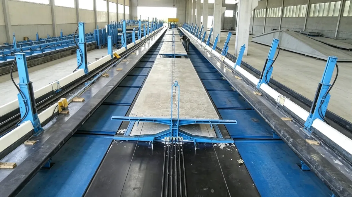
Steel Moulds for Precast Floor and Roof Slabs
Project-specific steel mould systems developed around your slab geometry, production arrangement and factory requirements.
- Designed around the finished slab
- Fixed or movable production arrangements
- Adjustable details where required
Start with the slabShow us the component you need to produce.
Define the production routeFixed or movable arrangements are reviewed around your factory process.
Configure the detailsDimensions, edges, openings and cast-in items shape the mould.
What slab do you plan to produce?
Floor and roof describe where the slab will be used. The mould itself is defined by the slab geometry, project details and production process.
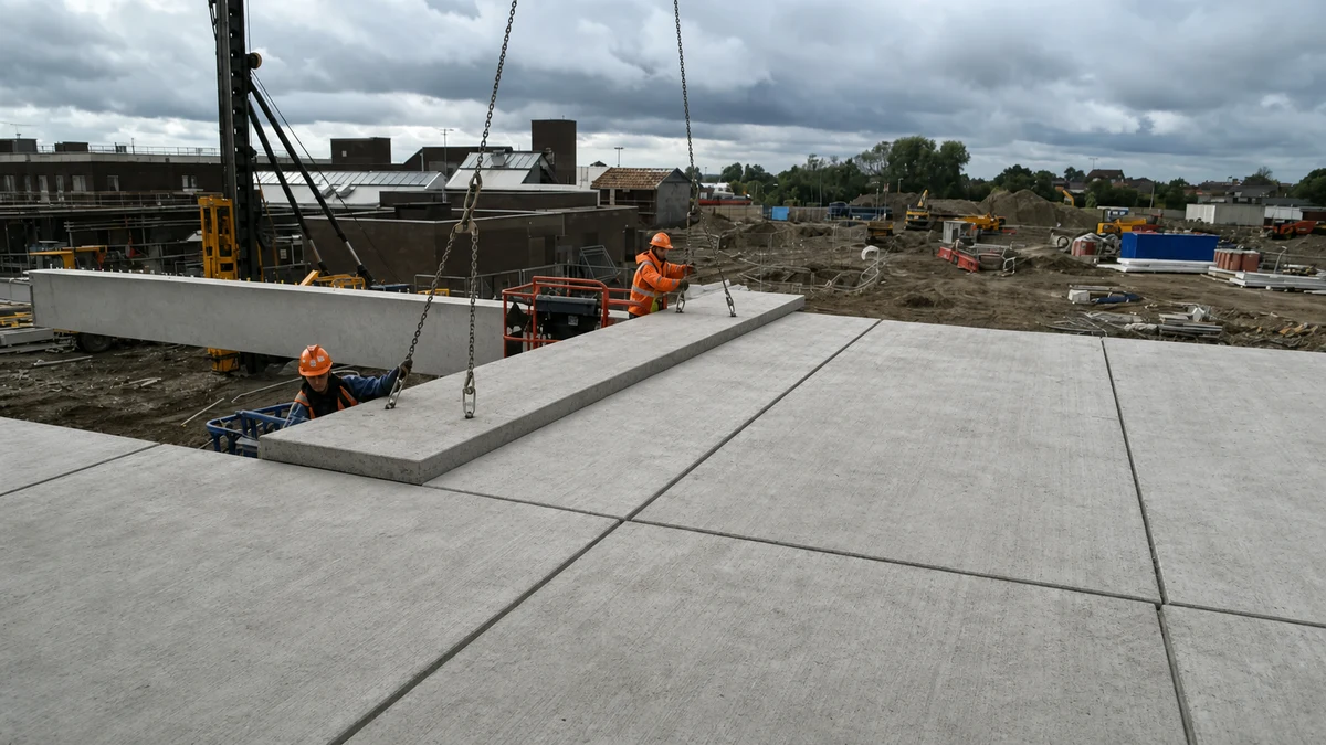
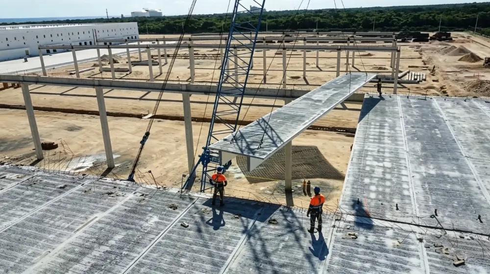
The application alone does not determine the mould. A floor slab and a roof slab may use a similar production arrangement. We review the actual component before recommending the mould direction.
The slab details come before the mould mechanism
The same basic slab can require a different mould when its dimensions, edges, openings, cast-in items or release method change.
A slab photo, approximate dimensions or an early drawing is enough to start.
- Slab type and geometryApplication, length, width, thickness, cross-section and the required range of variants.
- Edges, openings and cast-in itemsProfiles, recesses, penetrations, sockets, plates, lifting anchors and their reference positions.
- Casting and releaseVisible face, concrete placement, curing, demoulding and lifting direction.
- Factory processAvailable space, handling equipment, station sequence and target production cycle.
Built for repeat precast production in a factory
This page covers project-specific steel mould systems—not finished slab supply, site formwork or small paving moulds.
Defined slab family
You have a known component type, initial dimensions or a related range of slab variants.
Repeatable details
Edges, openings and cast-in items need controlled positioning across repeated production.
Factory production
Casting, curing, release, lifting and stacking must work as one production sequence.
Specialised slab system? Hollow-core extrusion, double-tee, half-slab, lattice-girder and prestressed long-line production require a separate technical review. Tell us the exact slab type so we can confirm whether this mould scope applies.
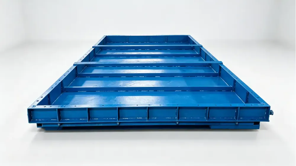
Choose how the slab will move through production
The first decision is whether the casting surface remains at one station or moves between production stages.
- Stable slab families
- Defined casting and lifting access
- Factory space organised around the table
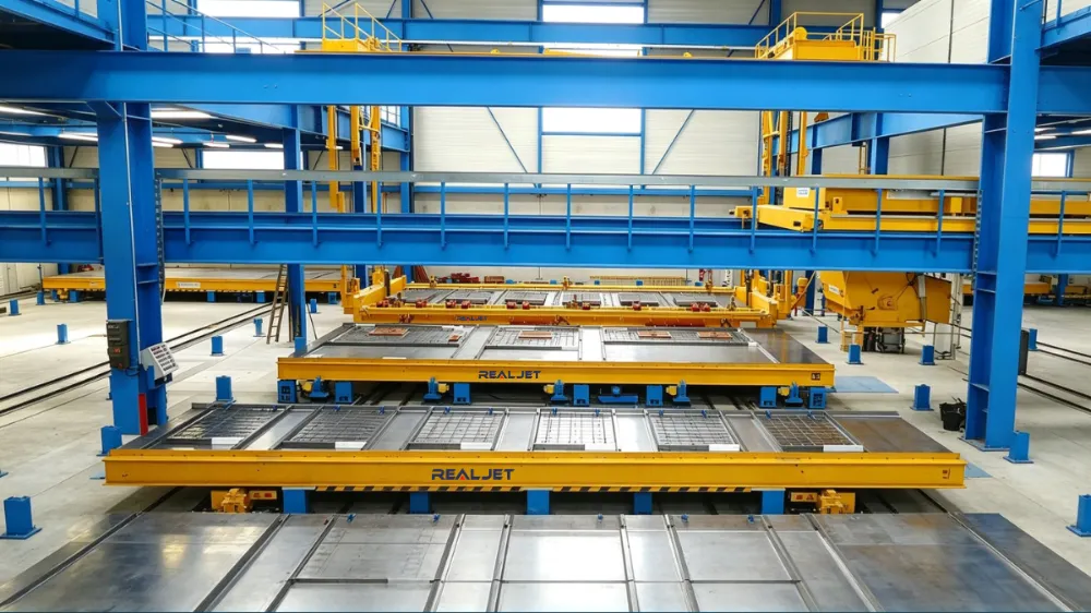
- Planned travel route and positioning
- Station and utility interfaces
- Handling and safety sequence
Add only the functions your slab requires
These functions are reviewed after the slab family and production arrangement are understood.
Adjustable side and end forms
For approved dimensional changes within a related slab family.
Replaceable inserts
For openings, recesses, sockets, plates and other local details.
Hydraulic functions
Reviewed where powered opening, lifting or adjustment supports the agreed operating sequence.
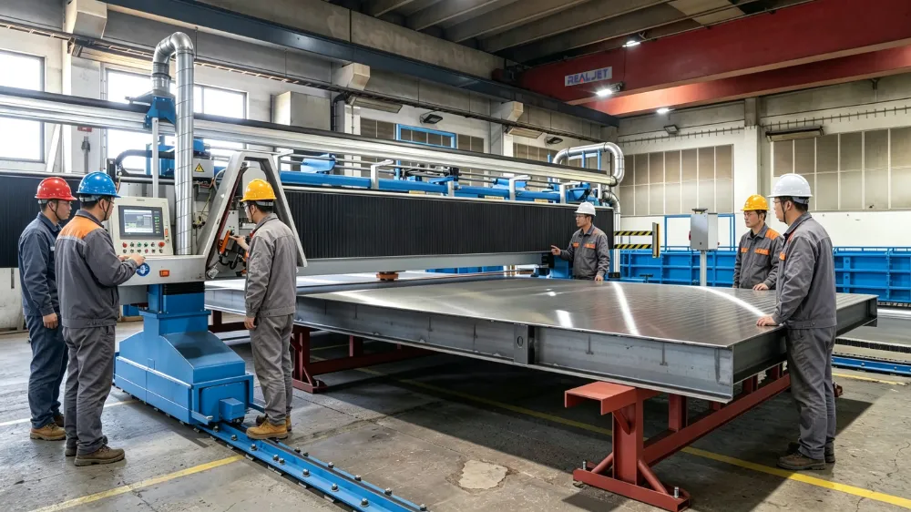
Turn the slab requirements into a manufacturable mould
Realjet connects process review, mechanical design, steel fabrication, mechanical or hydraulic integration, workshop assembly and inspection.
Final dimensions, tolerances, functions, interfaces and delivery boundaries are confirmed in the approved project documents before manufacturing.
One team connects the slab, the mould and the manufacturing route
A custom slab mould is not just a welded steel structure. Its geometry, operating sequence, fabricated parts and acceptance requirements must work together.
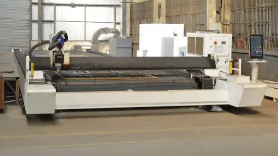
Drawing-led engineering
Slab geometry, production constraints and available drawings are reviewed before the mould scope is defined.
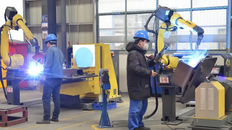
Connected fabrication
Cutting, forming, welding, machining and surface treatment are coordinated around the approved mould design.
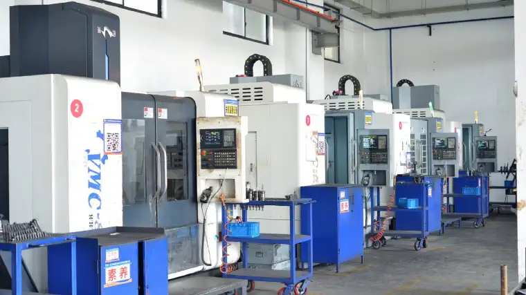
Integrated assembly
Structural parts, adjustable details and mechanical or hydraulic interfaces are brought together for workshop assembly.
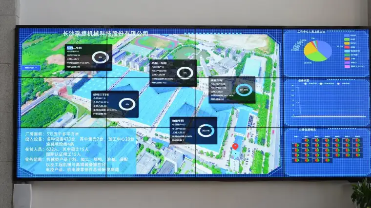
Inspection against the scope
Critical dimensions, interfaces, finish and final condition are checked against the agreed project documents before release.
Start with what you already know
You do not need to select the mould mechanism before contacting us.
- STEP 01
Show the slab
Send a component photo, approximate dimensions or an available drawing.
- STEP 02
Review the production process
We discuss variants, openings, casting, release, handling and factory constraints.
- STEP 03
Confirm the mould scope
Drawings, functions, interfaces and delivery boundaries are confirmed before manufacturing.
Questions before you send an enquiry
Start with a photo, dimensions or a drawing. The detailed mould scope can be developed during the technical review.
Can one mould produce different slab sizes?
Related sizes may be covered with adjustable side forms, end forms or stops within an approved slab family. The practical range depends on the slab geometry, openings, inserts and production method.
Can the mould include openings and cast-in items?
Project-specific formers and positioning details can be reviewed for openings, recesses, sockets, plates and lifting anchors. Their location and release direction must be confirmed from the slab drawings.
Do I need complete slab drawings before contacting Realjet?
No. A component photo, approximate dimensions or an early drawing can start the discussion. Approved technical documents are required before final design and manufacturing.
Should I use a fixed table or a movable pallet?
That depends on the slab family, output, factory layout, curing route, handling equipment and station sequence. We review the production process before recommending an arrangement.
Can hydraulic functions be included?
Hydraulic opening, lifting or adjustment can be reviewed where it supports the agreed load and operating sequence. The final scope depends on safety, controls, interfaces and maintenance requirements.
Is this page for hollow-core or prestressed slab production?
Not by default. Hollow-core extrusion, slipforming and prestressed long-line production follow specialised production routes. Share the exact slab type and process so the required equipment scope can be reviewed separately.
Show Us the Slab You Plan to Produce
Send a photo, approximate dimensions or an available drawing. We can review the slab details and production process before defining the mould direction.