
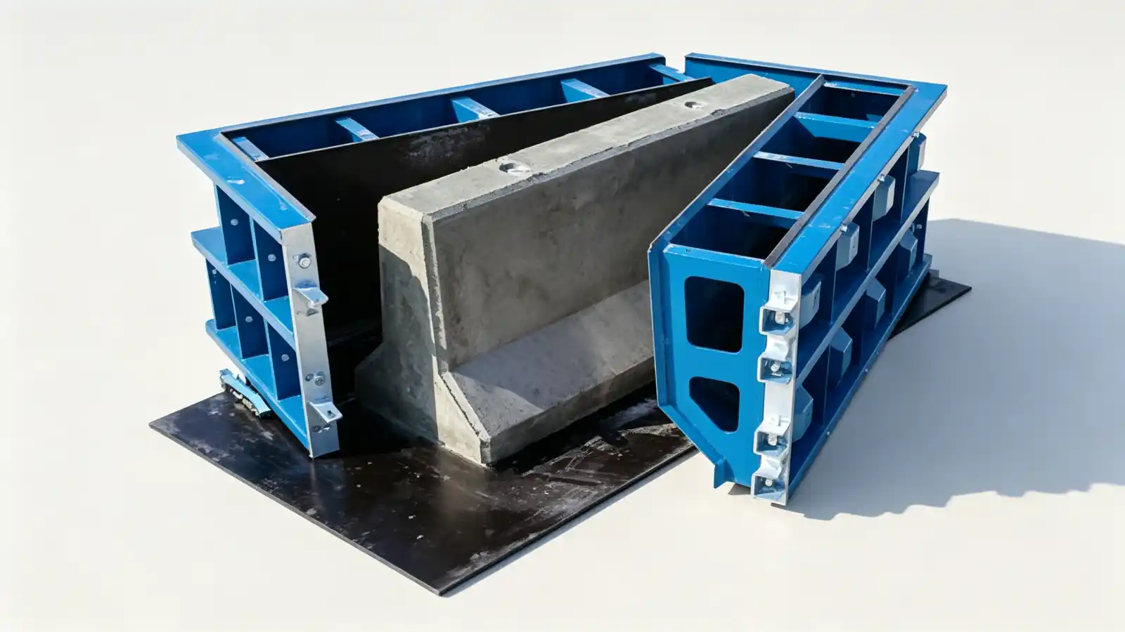
Barrier profiles a mould must form
A concrete safety barrier is defined by its cross section, not by its length. The mould has to form the face geometry exactly, because the slope is what redirects a vehicle instead of stopping it. The precast concrete mould range covers barrier and kerb tooling, but the approved profile has to be fixed before a mould can be engineered.
Three profiles dominate highway work. The New Jersey shape starts with a 3 inch vertical face at the pavement, breaks to a steep lower slope, then rises to a near vertical upper face. The F shape keeps the same idea but moves the break point lower, which reduces how far a car climbs on impact. The single slope keeps one constant face angle and is easier to overlay during road resurfacing. The Municipal and Infrastructure Moulds category groups these barrier tools with drainage, manhole, pipe and kerb moulds.
Face slope, toe and break point
The lower slope is the part a tyre meets first, so its angle sets the redirect behaviour. The FHWA roadside guidance explains that the Jersey lower slope breaks about 13 inches above the pavement while the F shape breaks about 10 inches higher up, and that the F shape was engineered to limit rollover for small cars (FHWA barrier guidance).
For the mould buyer this is a drawing issue. The toe height, the lower slope angle, the break point height and the upper face angle must all come from the approved barrier section. A mould built to a generic safety shape will not match a project that specifies F shape, and a mismatch forces site modification or rejection. State the exact profile and the standard it satisfies.
End joints and connection
Barrier units connect end to end, and the end form has to form the joint the project uses. Some barriers pin together, some overlap, and some use a keyed or tongue joint. The end form also carries any asphalt key, reveal or drainage feature called for in the section.
These details belong in the drawing review before fabrication, not as a site cut. Waterstop grooves, gasket profiles and keyways must be built into the end form or the side form, and the supplier needs the joint standard named so the formed edge is correct. The published road barrier and kerb mould product page is the reference for how Realjet configures these tools around the approved profile.
Surface texture and finish
The barrier face may need a specific texture for paint grip, reflectivity or appearance. A bare steel mould gives a smooth face; a textured or profiled liner gives a patterned one. State the required finish and whether it applies to the whole face or only the upper portion, because the liner and the release agent change with it.
Finish also affects demoulding. A deep texture can hold the concrete if the taper is wrong, so surface requirement and demoulding taper should be specified together. The buyer, not the supplier, owns the final appearance spec, and the RFQ should say which face gets which treatment.
On a multi profile programme the textured liner is specific to one face treatment, so confirm whether the run is one profile or several before the form is detailed. Changing liner mid run adds stop time, and the supplier should state the changeover in the cycle rather than hide it in the quoted output.
Demoulding taper and operation
A barrier mould opens along the face and the top. The taper, the part of the section that leans away from the concrete, lets the form release without scraping the face. Too little taper and the unit sticks; too much and the section drifts from the approved geometry.
Operation can be conventional, hydraulic or movable, and the choice follows output and handling, not the profile. A hydraulic or movable form helps on high volume runs where opening and closing time drives the cycle. Pick the operation after the profile and the quantity are fixed, because changing the form type later means re-engineering the frames.
What to send with the RFQ
A useful barrier mould enquiry includes:
- approved barrier profile, with the named standard (Jersey, F shape or single slope);
- toe height, lower slope angle, break point and upper face angle;
- section length, base width, height and the unit mass;
- end joint type, connection, reveal, keyway or drainage feature;
- surface texture and which face carries it;
- demoulding taper and the preferred operation type;
- reinforcement and embedded items the form must locate;
- target output, casting orientation and the planned mould quantity;
- required workshop trial assembly, inspection and delivery scope.
Fix the profile first. The mould follows the approved section, and a supplier response that glosses over the face geometry will not produce a barrier that passes the project's acceptance.