
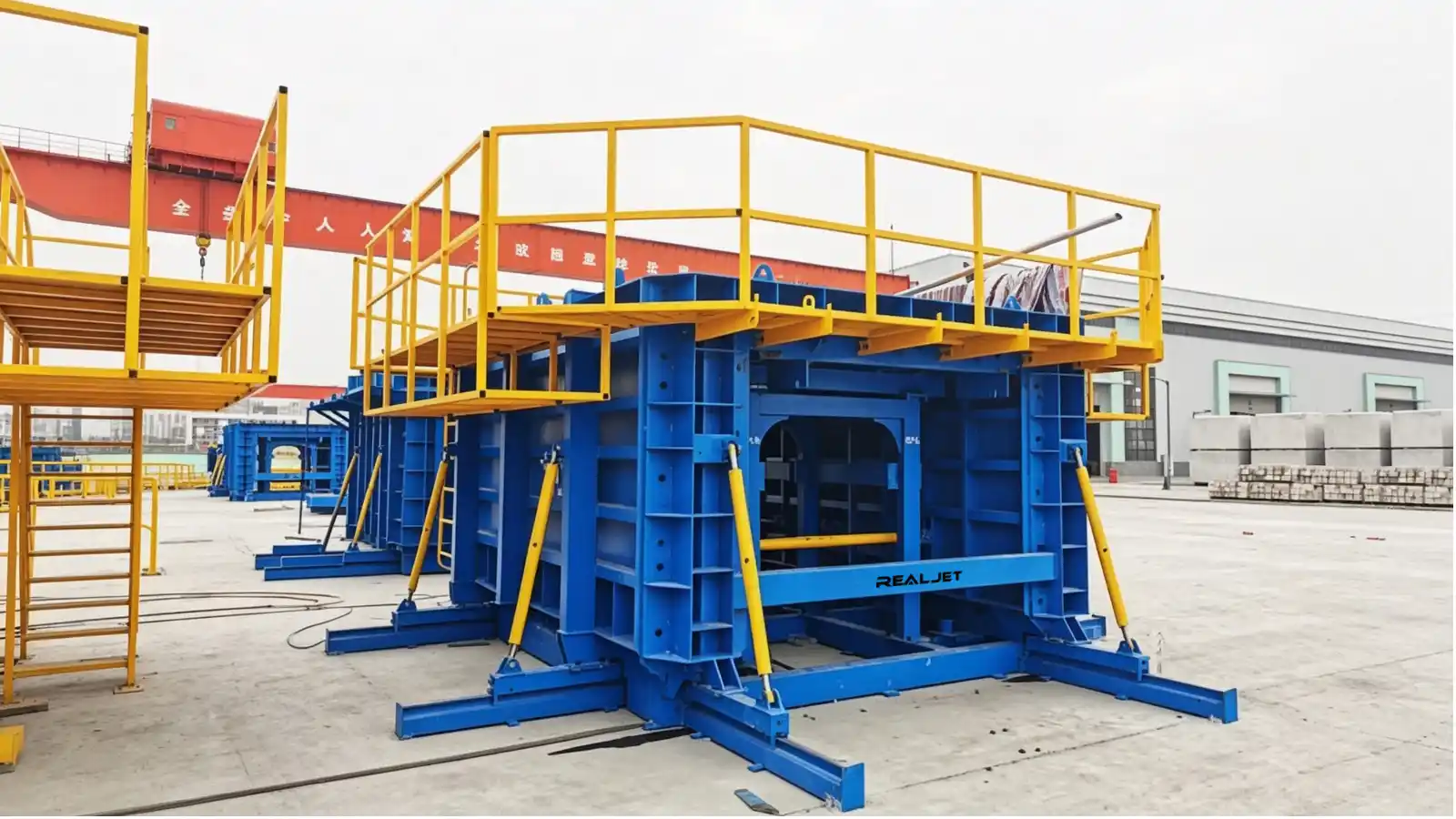
Single-cell and multi-cell box culverts
A precast concrete box culvert is a buried structure with two side walls, a top slab and a bottom slab. A single-cell culvert has one enclosed box. A multi-cell culvert has two or more cells separated by internal walls. Both are used for drainage crossings, utility corridors and underpasses.
The cell count is a design decision made by the project engineer, not by the mould supplier. The precast concrete mould range covers the tooling for either arrangement, but the approved drawing must state which one the production run requires before a mould can be engineered.
How cell count changes the mould
A single-cell mould is built from an outer shell and one internal core that forms the cell. The core must withdraw cleanly without striking the fresh concrete. A multi-cell mould adds shared walls and a core for each cell, plus internal wall formwork and more complex end forms.
The extra internal walls change the demoulding path. Each core needs clearance to move out of its cell, and the internal walls need a joint and sealing detail at the form face. A mould designed for a single cell cannot simply be subdivided later without re-engineering the cores and end forms.
The Tunnel and Underground Moulds category groups box culvert tooling with other buried-infrastructure moulds, and the published box culvert mould page is the product reference for this family.
Span, fill height and wall thickness
Clear span and fill height, the soil or traffic load above the structure, drive the wall and slab thickness and the reinforcement. Those dimensions set how much steel the mould carries and how stiff the frames must be.
The mould follows the approved geometry rather than a nominal rectangle. Two culverts with the same outside width can need different side-wall tapers, haunches or slab thicknesses, and each difference affects the side form and end form. ASTM C1433, the specification for precast reinforced concrete monolithic box sections for culverts, storm drains and sewers (current edition C1433-25), is the common US purchasing reference and it covers single and multi-cell sections.
Joints between cells and waterstops
Multi-cell structures introduce joints at the internal walls as well as the external joints between units. Waterstop grooves, gasket profiles and keyways are project-specific and must be built into the end forms or internal wall forms rather than cut on site. Standards such as ASTM C1677 for rubber gaskets and ASTM C990 for preformed flexible joint sealants are referenced in the ASTM C1433 purchasing chain and should be named in the RFQ so the supplier builds the correct groove.
A mould that cannot form the required joint or waterstop will force a site modification, which slows the cycle and risks the section. The joint and sealing requirements belong in the drawing review before fabrication.
Production impact and mould quantity
Multi-cell tooling usually needs more core and form pieces, a longer closing and opening sequence and more handling space than a single-cell tool of the same outside width. That affects the cycle and the number of moulds needed for a given output.
Map the activities that keep a mould occupied: bed preparation, reinforcement and insert setting, closure, concrete placement, curing, opening, lifting, cleaning and inspection. A cycle that ignores cleaning and inspection will understate the mould count. The supplier can design around a stated release condition but should not invent one to make the equipment count look smaller.
Trial assembly in the workshop remains the most reliable check that a multi-cell core set fits the approved geometry and clears the internal walls. Skipping it trades a known workshop cost for an unknown site problem, and the cost of a misfit grows with the number of cells.
What to send with the RFQ
A useful box culvert mould enquiry for a single or multi-cell structure includes:
- authorised cell arrangement drawing, with revision and status;
- size schedule for each cell, span, fill height and wall or slab thickness;
- joint profile, waterstop or gasket standard, and any keyway detail;
- reinforcement arrangement, embedded items and lifting inserts;
- casting orientation, concrete placement and vibration method;
- authorised release condition and the standard the section must satisfy;
- target accepted output, working calendar and the planned mould quantity basis;
- approved lifting points, unit mass, crane data and the route to storage;
- dimensional and surface acceptance requirements;
- preferred mechanical or hydraulic operation where already decided;
- required workshop assembly, inspection, documents and delivery scope.
Ask each bidder to list every assumption and deviation. The proposal should separate mould supply from civil foundations, cranes, concrete equipment, curing systems, installation work and production support.
What to confirm before the RFQ goes out
Decide the cell count, span range and fill height from the approved design first, because they fix the mould layout. Then send the cell arrangement, size schedule, joint details and required output through the box culvert mould enquiry route so the response addresses the correct tunnel and underground mould and the boundary for the specific project.