
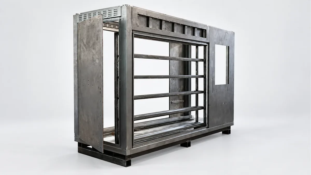
A frame arrives on site with the bolts in a crate and two holes on a splice plate sitting a few millimetres out of line. The erector reaches for a die grinder and the hole grows, and by the end of the shift somebody has to decide whether that connection still carries the load it was designed for. The argument that follows is expensive, and it usually traces back to two numbers the drawing never separated: hole clearance and hole position tolerance.
What the execution standard already fixes
EN 1090-2 treats a bolt hole as a designed feature rather than a by-product of cutting. Clause 6.6.1 defines nominal clearance as the difference between the nominal hole diameter and the bolt diameter, and the allowance scales with bolt size. For normal round holes the nominal clearance is 1 mm at M12 and M14, 2 mm from M16 to M24, and 3 mm at M27 and above. Oversize holes are wider still: 3 mm at M12, 4 mm from M14 to M22, 6 mm at M24 and 8 mm at M27 and above. Short and long slotted holes take their extra length on one axis only. A Swedish study of bolt clearance and joint resistance reproduces the EN 1090-2 clearance table and works through what the extra movement does to shear capacity.
Diameter carries its own tolerance. Holes for fit bolts and fitted pins are machined to H11, while thermally cut and other holes may deviate by plus or minus 0.5 mm. The standard permits drilling, punching, laser, plasma and other thermal processes as long as the finished cut face meets its quality requirements. Two holes can therefore comply and still cost very different amounts to produce.
Clearance is not the same as tolerance
Clearance is how far a bolt may sit off centre once it is through both plates. Position tolerance is how far the hole centre may sit from its nominal position relative to a stated datum. A generous clearance can absorb a small position error, and a tight position tolerance can make a small clearance work. Problems appear when one is specified and the other is left to the shop.
Where a drawing is silent, general tolerances apply, and a general tolerance on a frame six metres long is frequently larger than the bolt clearance. Site rework happens in that gap. If the position of a hole pattern matters, it needs a datum and a position tolerance to ISO 1101, not a note asking for accurate work.
How the hole is made sets what the frame can do
A guidance note from the Steel Construction Institute on hole sizes and positions for preloaded bolts sets out the methods fabricators actually use. Manual marking and drilling is acceptable for isolated hole groups. Match marking, where half the holes are pre-drilled, the parts are assembled, and the rest are marked through and drilled after dismantling, suits complex geometry. Bush templates give good accuracy inside a hole group but inherit general setting-out tolerance between groups. CNC plate drills produce an accurate group and accurate initial spacing, and then the inter-group dimensions move once the drilled plates are welded into the frame, because actual weld shrinkage differs from the allowance.
That note explains a question the enquiry should ask directly: are the holes made before or after welding, and if before, what shrinkage allowance was used? A fabricator drilling on the assembled and welded member removes that uncertainty at a cost. A fabricator drilling plates flat and welding afterwards is cheaper and needs a larger tolerance at the interface.
The stack-up over a long frame
Hole position tolerance applies to a pattern, and a pattern needs a single datum that both parties understand. Two plates drilled to the same tolerance from different edges can still miss each other at assembly. On a frame with several bolted interfaces, tolerance has to be apportioned along the chain, and one interface has to be nominated as the reference for the rest.
A buyer can save money here, before any steel is cut. Splitting a frame into more bolted joints adds adjustability and takes machining and welding capacity out of the factory, which usually costs more than the tolerance it buys. Keeping one long welded member and requiring tight hole position at both ends asks the fabricator to hold a tolerance over a distance that grows with temperature during the day.
Galvanizing takes clearance away
Hot dip galvanizing reduces the hole. ISO 1461:2022 sets minimum mean coating thickness of 85 micrometres on steel 6 mm and thicker, 70 micrometres from 3 to 6 mm, and 55 micrometres from 1.5 to 3 mm. The coating forms on the wall of the hole as well as the faces, so the diameter closes by twice the coating thickness. At 85 micrometres that is 0.17 mm of diameter, which is roughly 8 percent of the 2 mm clearance allowed on an M20 bolt. On a long bolt group the loss is felt at the far end of the pattern.
Threads need a decision as well. Galvanizing fills a thread unless it is masked or the nut is over-tapped, and fasteners for galvanized work are usually supplied to their own standard rather than being treated with the frame. Ask whether holes are drilled to final size before galvanizing, and whether anything is reamed afterwards.
Galvanizing also changes the friction surface. Slip-resistant connections depend on a declared surface class, and a galvanized and swept surface does not behave like blast-cleaned steel. If the joint is designed as slip-resistant, the coating specification and the joint design have to be agreed together.
Preloaded joints raise the bar
A preloaded assembly holds the connection by clamp force, so the hole has to stay round and the faces have to stay in contact. Aligning holes with a drift elongates them, which is why EN 1090-2 limits drifting rather than banning it, and why a preloaded joint that has been drifted hard should be questioned rather than accepted. Oversize holes in preloaded connections require hardened plate washers under the turned part.
The practical consequence for an enquiry is that the joint type belongs on the drawing. A non-preloaded bearing connection, a slip-resistant connection and a fitted bolt connection can look identical in a section view and impose three different levels of hole quality, inspection and cost.
What to put in the enquiry
| Item | What to state |
|---|---|
| Bolt size and grade | Nominal diameter, property class, and whether the assembly is to a preloaded or non-preloaded bolting standard |
| Hole type and diameter | Normal, oversize, short slotted or long slotted, with the diameter written as a number |
| Position tolerance and datum | The datum faces used for setting out, and the tolerance applied to each hole group |
| Joint type | Bearing, slip-resistant or fitted, and the slip factor if the connection relies on friction |
| Surface treatment sequence | Whether holes are drilled to size before galvanizing, and what is masked or re-tapped |
| Mating parts | Whether the counterpart is on the same order, another supplier's scope, or already on site |
| Drilling expectation | Whether match drilling or drilling after welding is required, and who pays for it |
Evidence that the pattern is right
A dimensional report on the finished member is more useful than a certificate of conformity. Ask for hole position records against the stated datum, diagonal measurements across rectangular patterns, and a note of the drilling method used for each interface. On a first order, a trial assembly with dimensional inspection catches a pattern error while the parts are still in the works, which is the only point at which correcting it is cheap.
Where the connection is machined as well as drilled, the same logic applies to the machined face. A machined interface specified separately from the hole pattern gives the shop two clear requirements instead of one vague one.
Who owns which decision
| Decision | Owner | Why it sits there |
|---|---|---|
| Bolt size, joint type and hole diameter | Designer | Follows from the connection design and the loads |
| Position tolerance and datum | Designer, agreed with the fabricator | The shop has to be able to hold it on its own equipment |
| Drilling method and sequence | Fabricator | Depends on machine capacity and welding sequence |
| Galvanizing and masking | Agreed between buyer and fabricator | Affects fit, threads and the friction surface |
| Site fit-up and any reaming | Erector | Happens after delivery and changes the connection |
| Acceptance of a drifted or opened hole | Designer or engineer of record | A structural judgement, not a commercial one |
Where to take the question
Hole patterns sit at the boundary between design and fabrication, which is exactly where a made to drawing contract manufacturing supplier and its customer need to agree in writing. Frames, base structures and machine supports produced to customer drawings, including the structural steel fabrication scope, are the cases where this conversation pays for itself before the first plate is cut.
If the drawing set is still being assembled, the more useful starting point may be the hole schedule rather than the frame geometry. A pattern that is dimensioned from one datum, with clearance and position tolerance separated, is a pattern that can be quoted, drilled, galvanized and bolted without a site argument.