
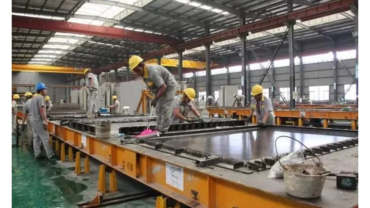
A girder mould is a large steel tool that arrives in pieces and is expected to produce a straight, correctly cambered member on its first cast. Whether it does depends less on the mould than on what it is standing on. The bed, the anchorage and the way the two are allowed to move relative to each other set the geometry before a single strand is stressed. Buyers who treat the bed as civil work and the mould as equipment tend to discover the connection between them during the first cast.
The bed sets the geometry before the mould does
Precast producers inherit a bed or build one, and the specification usually arrives with the project rather than with the equipment. Highway specifications show how tight the requirement can be. A state transport department requirement for prestressed members limits form movement to 6 mm from a straight line in any 15.25 m length and to 2 mm of offset where form sections are joined, with a bond breaker applied before every casting (Montana DOT 553). A transport authority specification for cast-in-situ girders on a fixed casting bed requires every point on a soffit sliding surface to sit within 2 mm of the specified level, the difference in level between the two soffit surfaces at any section to be within 1 mm, and the deviation from the specified slope not to exceed 1 in 1000 (Transport for NSW B152).
Those numbers are a useful reality check for a buyer comparing quotations. A mould built to hold a section to a few millimetres cannot correct a bed that is out of level by ten. If the enquiry contains the product but not the bed, the finish tolerance in the contract belongs to a party who cannot deliver it alone.
Stiffness matters as much as level
Level is measured with the bed empty, and a bed also has to stay level while it is loaded. Iowa's standard specification for precast and prestressed concrete requires casting beds to be rigidly constructed and supported so that there is no vertical deformation under the mass of the concrete and the vertical reactions of hold-downs and hold-down devices, and requires pretensioning end anchorages to resist the maximum prestress force without permanent displacement (Iowa DOT 2407).
That single sentence explains two failures that otherwise look like mould defects. A bed that deflects between supports changes the camber of every member cast on it, and a bed that settles permanently at an anchorage loses prestress force that the elongation record will not explain. Both are measured at the bed, and neither can be corrected by adjusting the mould.
The prestressing force belongs to the bed
In a pretensioned long line the strand is stressed between anchorages, and the reaction goes into the bed or into a self-reacting frame. Some bed designs carry the force through external abutments. Others are self-reacting, with the stressing force contained within the bed structure itself, which removes the abutment but concentrates the load path into the bed fabric. Either arrangement has a consequence for the mould: the mould is not a structural member in that load path, and it should not be asked to act as one.
A mould that is bolted hard to the bed at both ends becomes a tie between two points that move apart when the strands are stressed. The usual result is a side form that bows, a width that varies along the member, or a fixing that works loose over a few cycles. The detail that avoids it is a longitudinal freedom at one end, a slot or a sliding shoe, so that the mould follows the bed rather than resisting it. This is the kind of interface that should be drawn and agreed rather than left to site.
Temperature moves steel and concrete differently
Long beds concentrate thermal movement. Iowa's specification addresses it directly for long beds producing multiple pretensioned beams, requiring precautions to prevent damage to the beams from differential movements of forms and concrete caused by temperature changes.
The arithmetic is simple. Steel expands by roughly 12 millionths per degree Celsius, so a 40 m mould moves about 9.6 mm over a 20 C swing between a cold morning and an afternoon casting. Concrete moves at a similar rate once it has set, which means the risk is concentrated in the hours when the steel is warm and the concrete is still green, or when one part of the mould is in shade and the rest is not. An anchorage that is fixed at one end and sliding at the other can accommodate this. A mould clamped at every fixing point cannot.
Fixing methods and what each asks of the plant
Four arrangements cover most installations, and they differ in what the plant has to build before the mould arrives.
| Arrangement | What the plant provides | What it suits |
|---|---|---|
| Cast-in channel or embedded plate | Set out to a drawing, at a defined level, before the bed concrete is poured | Beds built for a known mould, where the position is fixed early |
| Resin or mechanical anchors into a finished bed | A sound, level bed and a drilling and setting procedure | Existing beds, or positions that may change |
| Clamp plates over a fixed rail | A rail set to line and level, with the mould free to slide along it | Long lines where longitudinal movement has to be allowed |
| Levelling screws and a grouted base | A base pour after alignment, with grout access | Moulds that need fine adjustment after installation |
Each arrangement has a cost and a failure mode. Embedded plates are accurate and unforgiving. Anchors are flexible and depend on the bed being sound. A rail with clamps allows movement and introduces a sliding interface that has to be kept clean. Grouting gives the best final level and makes later adjustment difficult.
Setting out and the first alignment record
Alignment starts from a datum both parties accept. On a long bed that is usually a survey line or a tensioned wire along the line of the member, with a transverse reference at the stressing end. The mould is set to the datum, checked for straightness along its length, checked for width at several sections, and checked for level at the ends and at mid span.
The record of that check is worth more than the check itself, because it is the reference for every later dispute about whether the mould moved or the bed did. Take levels and offsets before the first cast and repeat them after the first few cycles, when the mould has been stressed, vibrated and stripped. A change between the two records points at the anchorage rather than the fabrication.
What the mould can hold and what it cannot
A steel mould can hold a cavity dimension and a section profile within the tolerance agreed against the component drawing, which is how mould tolerances are normally set for a production line order. It cannot hold a line over 40 m if the bed under it is moving, and it cannot hold a level if its own base frame is shimmed to compensate for a bed that falls away.
The practical division is easy to state. The bed, the abutment and the anchor positions are the plant's scope, and they should be built and recorded to a stated tolerance. The mould body, the cavity, the side form geometry and the end forms are the supplier's scope. The joint between them, meaning base frame, fixing detail, slots and levelling arrangement, is where the two scopes meet, and it should be named in the contract rather than assumed.
Who owns which interface
| Interface | Owner | What has to be agreed in writing |
|---|---|---|
| Bed level, line and stiffness | Plant, to the project or equipment tolerance | The tolerance value and who verifies it |
| Anchor positions and levels | Plant, from the supplier's setting-out drawing | Drawing issue date and approval before pouring |
| Base frame, slots and levelling detail | Mould supplier | How longitudinal movement is accommodated |
| Alignment of the assembled mould | Joint, supervised by the supplier | Acceptance record and who signs it |
| Movement after stressing | Plant and supplier together | Expected movement and the limit that triggers action |
| First cast dimensional check | Plant, with supplier attendance | Dimensions measured, method and acceptance limits |
What to send with the enquiry
A mould enquiry that includes the bed drawing gets a more useful answer than one that includes only the girder section. Send the bed layout with the anchor positions if they exist, the length of the casting line and the number of mould sets, the stressing arrangement and where the abutments or self-reacting frame sit, the prestressing force and the strand pattern, the range of sections and lengths to be produced, and the tolerance the finished member has to meet.
Say also whether the bed already exists or is being built. A new bed can carry embedded plates set out to the mould drawing. An existing bed constrains the anchorage to what can be drilled and fixed, and that changes both the mould base frame and the installation sequence.
The first cast is the proof
The first member tests everything above. Camber, sweep, section width, soffit level and joint offsets are measured on that first unit and compared with the values predicted from the design. If the member is outside tolerance, the measurement that matters is the one taken on the mould before stripping, because it separates a bed problem from a mould problem.
A girder mould system for a precast production line is normally designed around the section, the casting method and the plant layout, and the base frame detail follows from the bed it will stand on. Buyers comparing bridge and transportation mould systems across suppliers should compare the anchorage detail as carefully as the cavity, since the cavity is what every supplier quotes and the anchorage decides whether the first cast is right.
The wider precast concrete mould range shows how much of the geometry is project specific, and how little of it can be separated from the plant it will run in. Where the mould is one element of a larger precast production line package, the bed and anchorage interface is worth writing into the scope split before the purchase order, because it is far cheaper to draw than to correct.