
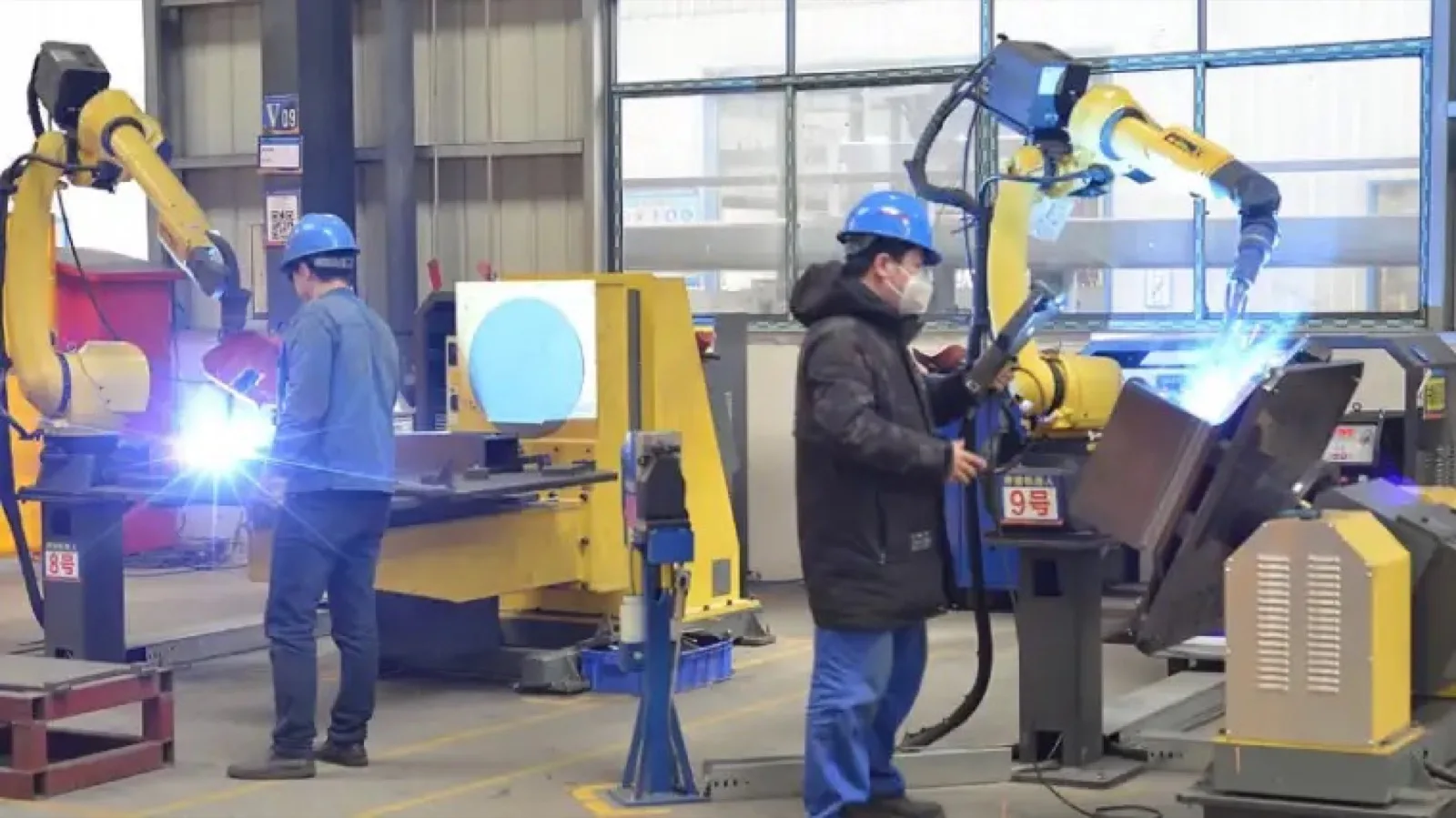
What a machined interface means on a fabricated part
A machined interface is a precisely finished feature on a welded or fabricated structure that other components locate against. Typical examples are a bolt hole pattern, a bearing seat, a shaft journal, a mounting face, or a dowel located datum. The surrounding structure may be welded plate and section, but only the interface needs tight control. Buyers evaluating contract manufacturing should understand this term because the RFQ, not the supplier, sets which features are critical. Knowing it helps you write a clearer RFQ and compare shops on the same basis.
Why welding and machining are planned together
Welding introduces heat and distortion. An as welded assembly typically holds looser tolerances than a machined part. General tolerances for welded fabrications often follow ISO 2768 class cK, while post weld machined surfaces are usually held to class mK or tighter. A supplier will often weld the structure first, then machine the critical interfaces in a fixture after the part has relaxed. If your drawing treats the whole part as one tolerance band, the shop will either over machine or quote a risk premium. State which faces are datums and which are cosmetic, and let a general tolerance cover the rest.
Use ISO 2768-1 for general tolerances and ASME Y14.5 for geometric dimensioning and tolerancing on North American drawings. These references explain how to call out tolerances, not what any supplier can achieve.
Typical ranges to brief your supplier with
The table below is general guidance drawn from common fabrication practice. Treat it as a communication baseline, then confirm the achievable range with the shop against your material, wall thickness, and fixture method.
| Condition | Typical linear tolerance | Notes |
|---|---|---|
| As welded structural assembly | about plus or minus 1 to 2 mm | Distortion depends on heat input and fixturing |
| Welded then machined interface | about plus or minus 0.05 to 0.1 mm | Held only on the finished faces |
| General toleranced features | ISO 2768 class cK or mK | Set the class in the drawing title block |
The numbers describe process capability, not a guarantee. The same nominal tolerance can behave differently after bending, welding, and assembly, so protect the few features that actually matter.
What to put in the RFQ
List the inputs a shop needs to quote and plan:
- Controlled drawings in 2D and 3D, with the critical interfaces clearly marked and datum references assigned.
- A bill of materials with material grades, plate thicknesses, and certification requirements such as mill certs or EN 10204 3.1.
- Welding specification: an applicable standard such as ISO 3834 for fusion welding quality or AWS D1.1 for structural steel, including weld procedure, welder qualification, and any non destructive testing.
- Tolerances: an ISO 2768 class for general dimensions, plus geometric dimensioning and tolerancing per ASME Y14.5 or the project standard for the critical interfaces, and a machining allowance if material removal is expected.
- Surface finish, coating, and any sealing or hardness requirement on the interface.
- Quantity, delivery schedule, packaging, and the inspection evidence you expect with each batch.
Drawing and model readiness before you invite quotes
Before sending the RFQ, confirm the package is complete enough to quote without assumptions. The drawing should name the general tolerance standard and class, assign datums to real mating surfaces, and call out the critical interfaces with feature control frames rather than a blanket tight number. The 3D model should match the 2D, and the bill of materials should list every plate, section, fastener, and inserted item with its material and certification. Welding symbols should state the joint type, inspection level, and any post weld heat treatment. When these are missing, shops either quote conservatively or ask a long chain of questions that slow the whole sourcing process.
Who is responsible for what
The buyer or their design engineer owns the design intent: geometry, datums, functional tolerances, and the standard to apply. The contract manufacturer owns execution: cutting, welding, machining, coating, and the inspection records. Realjet supplies custom machinery components to customer drawings and specifications. It does not set the design or the acceptance limits. Final scope, tolerances, and acceptance remain subject to the approved project documents. A clear split in the RFQ prevents the most common failure, which is a part that passes inspection yet will not assemble because the datum used in the shop differed from the datum in the design.
A published example is the crane boom head manufacturing reference, which shows a welded structure finished with precision interface machining. It is not a standard catalogue part. Buyers ready to shortlist a supplier can send controlled drawings, materials, welding requirements, critical dimensions, quantities, and delivery terms through Realjet's construction machinery contract manufacturing service. Final scope and acceptance stay subject to the approved project documents.
Inspection evidence to request before acceptance
Ask for records that let you verify the interface without re measuring everything: a coordinate measuring machine report, weld procedure and welder qualification records, material certificates, and any non destructive testing reports called for by the specification. Request the evidence per batch or per first article, and name the format. The quality system behind those records is what keeps a welded and machined part repeatable across a long run.
Next step before you send the RFQ
Before releasing the RFQ, mark the three to five features that actually drive assembly, assign their datums, and let everything else sit under a general tolerance. That single step usually removes more cost and risk than tightening every number. When your drawings and bill of materials are ready, open a review with a supplier who manufactures to customer drawings and can return the inspection evidence your project requires.