
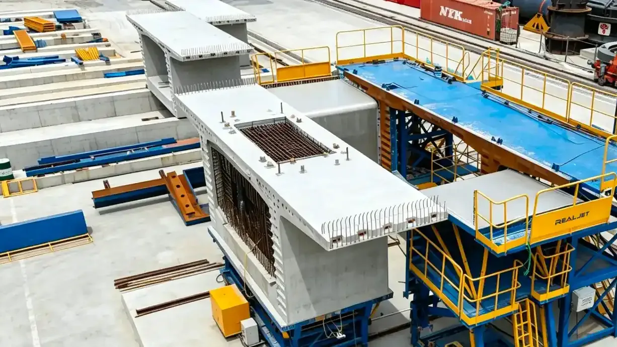
A box girder mould for a 30 m span arrives as a set of assemblies that have to travel, be lifted into a yard, bolted back together and then hold a concrete face straight enough for a bridge. The way it is divided is decided in the mould order, long before anyone measures the road, and it determines how many joints the finished girder will carry on its surface.
Buyers usually specify the geometry and leave the division to the supplier. That works when the yard sits next to the factory. It works less well when the mould has to cross a border, pass a weigh station or enter a site through a gate narrower than the mould is wide.
The division follows the route, not the drawing
A box girder mould is normally arranged as a bottom assembly, two side forms, end forms and an internal form. That division is driven by how the mould is used: the internal form has to be withdrawn, the side forms have to strip, the end forms have to be reset for each segment length.
Transport imposes a second division on top of the first. A side form 30 m long cannot be carried as one piece, so it is cut into sections that bolt together on site. Where those cuts fall, and how many there are, is a design decision with consequences for stiffness, alignment and cost. The buyer's job is to supply the route constraints early enough for that decision to be made properly.
What the road allows
In China, the threshold for oversize transport is set by the Ministry of Transport regulation on abnormal load vehicles on public roads. A vehicle and load wider than 2.55 m, higher than 4 m from the ground, or longer than 18.1 m is over the limit and needs a permit before it moves. Above 3.75 m width, 4.5 m height or 28 m length the application also requires an outline drawing and an escort plan.
The permit takes time to obtain. Approval takes two working days for loads within 3 m width and 20 m length, five working days up to 3.75 m and 28 m, and fifteen working days beyond that, and the route may be surveyed and strengthened before it is granted. A mould section that sits just over a threshold can add weeks to a delivery programme for a few hundred millimetres of width.
Most of the world's road networks use similar numbers. European limits sit at 2.55 m for vehicle width, which is why mould and formwork suppliers design road transportable sections around a nominal 2.4 m to 2.5 m envelope and treat anything wider as a project shipment.
Ocean freight has its own envelope. ISO 668 sets the series 1 container dimensions, and a 40 foot container gives roughly 2.35 m of internal width, 2.39 m of internal height and a 2.34 m door opening. A box girder side form with a deep stiffener rib will not pass that door as an assembly. Either it is broken down further into panels and ribs, or it travels as break bulk on a flat rack, which changes the packing, the lifting plan and the insurance.
What the split costs
Every additional joint is a place where the mould can move. Under fresh concrete pressure, a side form behaves as a beam supported at its stiffeners and restrained at its joints, and the joint line is the least stiff part of that beam. Two sections bolted together deflect more at the interface than a continuous form does at the same point.
The practical answer is not to minimise joints at any cost, because a mould that cannot be transported cannot be used. It is to put the joints where the consequences are smallest and to design them so they behave like a continuous member.
Three things make that work. The joint faces are machined flat and square, not flame cut, so the two sections close on metal rather than on a gap. Dowels or fitted bolts take the shear across the joint so the bolts are not relying on friction alone. And the stiffener pattern is arranged so that there is a heavy rib on each side of every joint, with tie rods or clamps pulling the two together near the top and bottom of the form face.
A joint placed where the girder has a diaphragm, a web thickening or an end block is easier to hide than one placed mid span, because the local stiffness is already higher and the surface is often not the visible face.
Trial assembly before dispatch
The strongest argument for trial assembly is that a joint which does not close in the factory will not close in the yard. Chinese quality guidance for bridge precast elements is explicit about it: the technical and management guideline for bridge precast component quality published by the Ministry of Transport asks for trial assembly at the mould factory before dispatch, with the client's representative present, and for acceptance of dimensions, surface flatness and joint offset before the mould is released.
That mirrors what a well run mould order does anyway. Realjet's box girder moulds are described as being divided into bottom, side, end and internal-form assemblies and verified by workshop trial assembly against an agreed inspection plan, so the dimensional record exists before the mould leaves.
What should be measured during that trial is worth stating in the order, because a trial that only proves the parts fit together proves very little. The list that matters:
| Check | Why it matters |
|---|---|
| Overall length and segment length settings | Sets the girder length and the match cast joint |
| Deck width and web position at both ends | Sets the cross section and the alignment of adjacent segments |
| Diagonals of each rectangular opening | Detects a mould that is square in plan but twisted |
| Joint offset at every bolted interface | A step at the joint becomes a step in the concrete |
| Flatness of the casting face | Governs the visible soffit and the bearing surface |
| Verticality of side forms | Governs web inclination over the full height |
Recorded numbers signed by both parties are the only useful output, because a trial assembly that produces a photograph and a verbal assurance is not evidence.
Site assembly and the first alignment record
On site the mould lands on a bed, a set of rails or a casting station, and the bed is where alignment starts. A bed that is level to a few millimetres over 30 m is not the same as a bed that is flat, and the difference shows up as a girder with a twist that cannot be corrected later.
The sequence that avoids trouble is unglamorous. Establish the centreline and a datum, place the bottom assembly and check it against both, bolt the side forms from the middle outward so the joints close progressively, then set the internal form and check the section at both ends and at mid span. Torque the joint bolts in the specified order, and record the readings before the first pour rather than after.
Responsibility for this work is a contract question, not a technical one. Some suppliers send an assembly supervisor, some send written instructions, some deliver ex works and expect the buyer's crew to do everything. All three are normal. What is not normal is leaving the split undefined until the mould is on the water. The internal form withdrawal sequence and the inputs a mould enquiry needs both depend on the same decision.
Grout loss at every joint
Fresh concrete finds gaps under vibration. A joint that looks closed will still pass grout, and the result is a fin on the girder surface that has to be ground back before anyone accepts the finish.
Two measures handle it. A compressible sealant or gasket in a machined groove at the joint face keeps the grout on the correct side, and a bead of sealant on the inside of the joint before closing does the same job where a groove is impractical. Neither replaces a joint that closes properly, and neither survives a joint whose bolts were tightened in the wrong order.
For an exposed soffit, the joint line is also where the finish argument starts. A fin that has been ground leaves a mark, and a bridge inspected in raking light will show every one of them. Buyers who care about the appearance of the soffit should say so when the mould is specified, because the answer is a better joint, not a better grinder.
What to put in the mould order
| Item | What to state |
|---|---|
| Route and destination | Port, road restrictions, site gate width, crane capacity at the yard |
| Maximum piece size | The largest single assembly that can be transported and lifted |
| Section divisions | Where the mould may be split, and the maximum number of joints |
| Joint standard | Machined faces, dowel type, bolt grade and tightening method |
| Trial assembly | Witness, measurement schedule, record format and acceptance limits |
| Site support | Who supervises assembly, and what documentation is handed over |
| First cast | Whether the supplier attends, and what is checked before release |
A mould bought as part of the bridge and transportation mould range is a long term asset, and the joints are the part of it that will be adjusted, re-shimmed and re-torqued for years. Getting the division right at the order stage is cheaper than correcting it in a yard.
Buyers still working out how the mould fits into a wider precast production line should settle the transport question first, because the envelope constrains the lifting plan, the yard layout and the cycle. Comparing a box girder mould with other precast concrete moulds is easier once that envelope is known, since the same sectioning logic applies to any long bridge mould.