
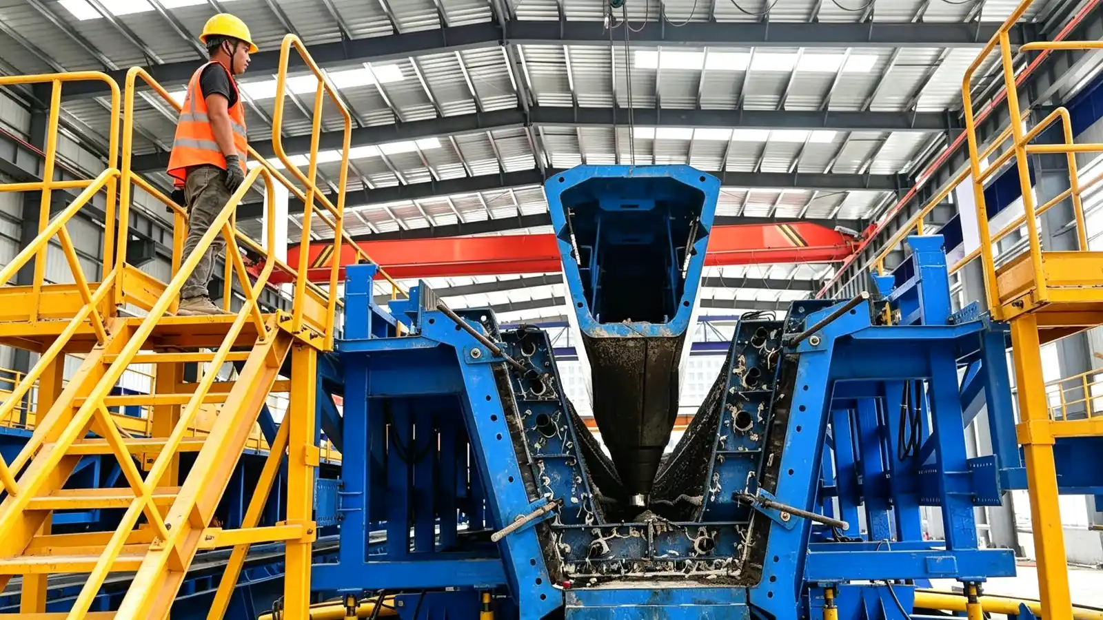
Box girder moulds are project specific tools
A box girder is a hollow superstructure element used in highway, railway and urban viaduct bridges. Its mould is a steel tool built around the approved section, not a catalogue item. Realjet supplies these moulds as part of precast concrete production lines; it does not sell the girders themselves. Because the cross section, cell layout and casting method change from project to project, the RFQ has to carry the project data that fixes the tool.
Section geometry and casting method inputs
The approved drawings define the external profile and the internal cell geometry: web inclination, deck width, cell number, diaphragm positions, prestressing ducts and lifting provisions. The casting orientation (span cast flat or on edge) and the length variants also shape the mould division into bottom, side, end and internal form assemblies. The buyer should attach the girder drawing and the component schedule. Standards such as EN 13369 for general precast concrete products and AASHTO LRFD Bridge Design Specifications for the structural section guide the design, but the geometry itself comes from the project's approved documents, not from the mould supplier. EN 13369 is summarised at https://en.wikipedia.org/wiki/EN_13369.
Demoulding, internal form withdrawal and handling
The internal form that shapes the box cell must be installed and withdrawn in a controlled sequence, so its operation is a central RFQ input. Conventional segmented forms are handled by crane and manual assembly; mechanised or hydraulic assistance is considered when the side or internal forms move repeatedly. A movable mould arrangement is reviewed when the production flow requires the mould to reposition along rails or a travel path. The buyer states the preferred operating method and the yard lifting plan, and the supplier reviews clearance, stroke, locking and controls against them. Power assisted movement also reduces the manual labour needed at each cycle, which matters where the crew is small or the box is large. The bridge and transportation moulds family covers box girders alongside other bridge components.
Concrete access, vibration and cycle time
The mould division has to leave room for concrete placing and internal vibration, because a box cell with webs and diaphragms is hard to fill without proper access. The buyer's target cycle time influences whether the internal form is quick to withdraw and whether the side forms move by power. A shorter cycle favours hydraulic or mechanical assistance, while a longer cycle can accept manual assembly. State the planned daily output and the demoulding time, and the supplier can match the mould movement method to the required pace.
Tolerances, finishes and embedded items
Final component tolerances follow the approved project documents and applicable standards such as EN 13369 and the PCI quality manuals (PCI MNL-116 for structural products, PCI MNL-117 for architectural finishes). The RFQ should state the dimensional tolerance class, the concrete finish requirement and the position of embedded items, because these decide where the mould needs machined stops, reference points and sealing details. Surface preparation of the steel contact face and the release agent method also affect the concrete appearance and are worth fixing in writing.
Mould quantity, transport and spare parts
The number of mould sets depends on the production cycle and whether the line runs single or multiple cells. State the required sets and any length variants, because they change the steel quantity and the workshop load. Large bottom and side forms can be out of gauge for road transport, so the buyer should confirm the route and any disassembly the mould allows. Wear parts such as seals, stops and hydraulic elements are worth listing as spares in the RFQ, with the supplier's recommended quantities, so the line keeps running after commissioning.
What Realjet supplies and what the buyer provides
Realjet engineers the steel mould to the approved geometry, plans segmentation around reinforcement and concrete access, integrates mechanical or hydraulic movement where required, and verifies dimensions through workshop trial assembly to an agreed inspection plan. The buyer provides the approved drawings, the component schedule, the tolerance requirements, the operating preference and the yard layout. The production method and the acceptance criteria stay with the project documents. If the approved drawings are still at preliminary stage, say so in the RFQ, because tooling that locks to an unconfirmed section risks rework, while a confirmed section lets the supplier commit to a delivery date. Review the box girder moulds product page for the configuration directions before you brief the supplier, then package the inputs above into one RFQ.
A box girder mould is only as good as the project data behind it. Gather the approved section, the demoulding preference and the tolerance class, then send one complete RFQ so the supplier can return a tool that matches the production line rather than a generic shell.