
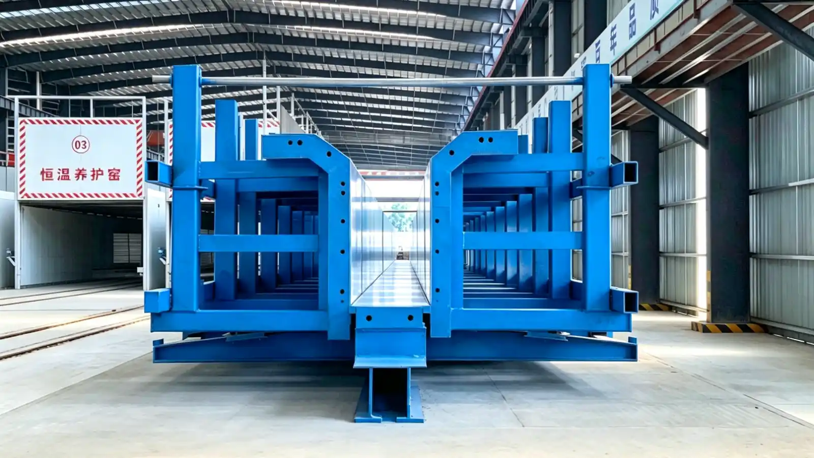
Why cross-section variety matters for the mould
A bridge project rarely uses one T girder section for its whole length. Spans, support conditions and erection sequences can call for different flange widths, stem heights or web thicknesses even when the girder family looks uniform on paper. The mould is the tool that holds those dimensions, so how you handle the variation decides cost, changeover time and dimensional repeatability.
This note is for bridge contractors, precast producers and formwork engineers who specify T girder moulds. It compares two common approaches, adjustable sections and dedicated moulds, and lists the drawings you should release before requesting a quotation.
Adjustable sections versus dedicated moulds
An adjustable mould carries movable or replaceable parts so one tool serves several related sections. Adjustable end forms, repositioned side forms and interchangeable inserts can cover a band of flange widths or stem heights without building a separate mould for each. The benefit is fewer tools and faster changeover between variants.
A dedicated mould is built for one section. It is usually simpler to set up, easier to verify, and less sensitive to operator error, but each new section adds a mould to buy, store and maintain. For projects with many one off sections, the tool count can grow quickly.
The choice tracks the number of variants, how often you switch between them, and how tight the tolerances are. A small family of related sections favours adjustability. A long run of one section favours a dedicated tool.
Cost follows from the same split. Adjustable tooling costs more to engineer but spreads that cost across variants, while dedicated tooling is cheaper per tool but multiplies with the number of sections. The break even point depends on how many variants you run and how long each stays in production, so state the expected mix when you ask for numbers.
What the mould must hold
The mould fixes the concrete geometry through casting, vibration, curing and stripping. Flange width, stem height, web position and end detail all depend on stable reference points and repeatable locking. PCI documents such as MNL-116 and MNL-117 describe plant quality and tolerance practice for precast and prestressed concrete, and MNL-135 collects the tolerances the industry uses as guidelines. Project drawings remain the controlling reference; the tolerances in those manuals are a starting point, not a fixed acceptance limit.
When sections vary, define which dimensions stay constant and which change. Constant surfaces can stay fixed in the mould, while changing surfaces move or get replaced. This split is the basis of a sensible adjustable design and of an accurate quotation.
Repeatability between cycles
A mould is judged by how consistently it reproduces the section after dozens or hundreds of casts. Adjustable features add moving parts and locking points, so they need a verification routine: check the setting dimensions against the reference points before each changeover, and record them. A dedicated mould has fewer things to check, which is why it suits a single long run.
Discuss with the supplier how the mould is set and how it is checked. The answer tells you how much operator skill the production plan will need and how the quality record should be kept.
Demoulding and stripping direction
Cross section changes can affect how the girder leaves the mould. A wider flange or a taller stem changes the stripping forces and the direction of withdrawal. State the casting position and the intended stripping direction, because they influence where the adjustable parts sit and how they are released. Precast MNL-117 notes that forms must be rigid enough to keep dimensions stable during placement and consolidation, which matters more when sections move.
Drawings and inputs for the RFQ
Send the girder cross sections for every variant, the length range, the prestressing method, the embedded item layout, and the tolerance expectations. Note where sections share geometry and where they differ. If you already know the casting sequence and the stripping direction, include them, because they affect how the adjustable parts are arranged.
Also state the production rate and the number of mould sets you expect to run in parallel. Adjustable features add engineering and moving parts, so a mould built for one section at high volume may be simpler and cheaper than a heavily adjustable one used rarely.
Responsibility boundaries
The design office owns the section and the tolerance. The mould supplier proposes how the tool achieves them and confirms what it can hold repeatably. The precast producer owns the daily setting, cleaning and checking between cycles. Realjet develops project specific T girder moulds from the approved drawings and production method, but the section approval and any project specific acceptance limits stay with the design and the buyer.
Where to continue
Browse the full set of precast concrete mould systems to see how mould families are organised. The bridge and transportation moulds category covers girders, segments and related bridge components. For the specific tool, the T-girder mould systems page shows how Realjet develops moulds around the approved section, length range and casting workflow.