
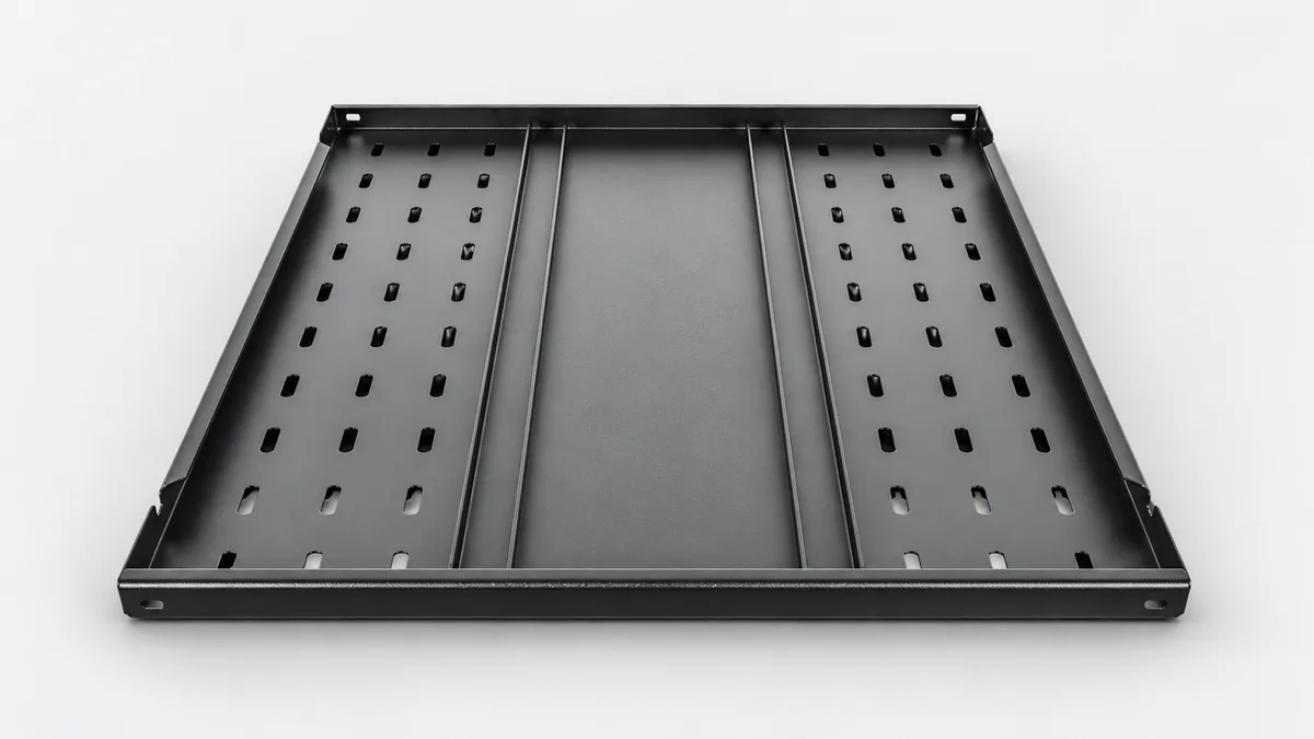
Battery Module Support Trays to your design
Order an external metal tray that supports your battery module in its rack or cabinet. REALJET forms the tray and adds drawing-defined reinforcement, mounting features and finish to suit your assembly.
Choose the part and delivery condition
| Your order | Information that sets the scope |
|---|---|
| Formed support tray | Module footprint, tray profile and mounting pattern |
| Reinforced tray | Support span, reinforcement and joining details |
| Tray with specified restraint features | Restraint attachment, insulation clearances and hardware |
This is an external module support, not a sealed battery pack enclosure, cell can or liquid cold plate. Battery modules, insulation parts and electrical connections are included only if explicitly listed.
Fit it to the equipment around it
Show the supported module footprint and where the tray transfers its load into the rack. Identify restraint holes, edge requirements and clearance around insulation parts. The support for a stationary BESS module is reviewed separately from an AI data-center backup module.
| Intended installation | Equipment interface to supply |
|---|---|
| AI equipment | AI data-center battery backup rack |
| Battery storage equipment | Stationary energy storage battery rack |
Plan the manufacturing around these features
The steps below are proposed for the drawing review. Your material, geometry and acceptance requirements determine the final route, tooling and inspection provision.
Review the support load path
Separate module contact areas from rack attachment and restraint holes. Review bend access, insulation clearances and the installed support span.
Form and reinforce the tray
Review the forming order and any reinforcement joining so the module contact plane is not accepted before the final joining operation.
Finish module-facing features
Deburr edges near insertion and insulation parts. Review coating on supports and fixings; insulation performance is not inferred from a painted surface.
Manufacturing capability for your component
| Your component feature | Existing process and its use | Confirm for your order |
|---|---|---|
| Tray and restraint features | Plate preparation and CNC bending. Form module supports and restraint features from the approved footprint and support span. | Tray tooling, edge geometry and insulation clearances. |
| Reinforcement | Welded fabrication with interface machining where specified. Review reinforcement before the final support-plane check; machine only locating features that require it. | Support height after joining and the final locating arrangement. |
| Module-facing finish | Deburring and surface-treatment routes. Protect the insertion and insulation-contact edges through finishing. | Finish compatibility and load/deflection test provision. |
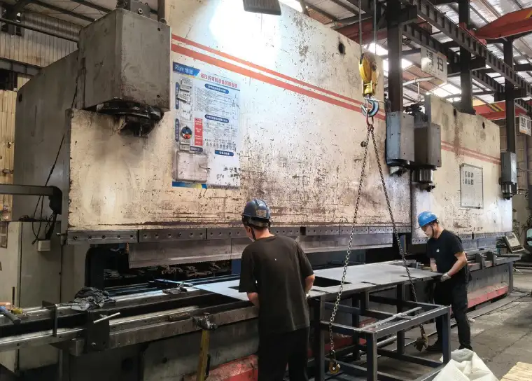
The existing forming and fabrication route is relevant to the tray. Support span, module contact and any loading verification need their own agreed setup.
Define what the first article must demonstrate
| Feature | Proposed check | Record to agree |
|---|---|---|
| Contact and attachment geometry | Locate the tray at its rack datums and measure support height, hole positions and the module footprint. | Support/attachment results and datum setup. |
| Module insertion and restraint | Use the nominated module or dummy to check insertion and restraint access, including the specified insulation clearances. | Fit checklist and module/dummy revision. |
| Deflection if ordered | Apply the agreed load distribution over the defined support span; record movement at nominated points and the unloaded condition. | Test mass, supports, measurement points and load/unload readings. |
Identify the drawing revision, measurement datums and pass/fail limits before the sample is made. The quote confirms the available measuring setup, any mating fixture and whether a specialist test needs an external provider.
Packing for your next assembly step
Protect formed edges and prevent the load of stacked trays from distorting support surfaces. State whether trays may be nested and how the finish must be separated. State the quantity and delivery city so packing volume and the requested delivery terms can be included.
Questions before you send drawings
What has to be defined for a tray deflection check?
The module mass alone is insufficient. Specify where the load acts, the rack supports and span, measurement positions and acceptance limits. The quotation must confirm the test fixture and measurement route.
Is this a sealed battery pack tray?
No. This product supports an enclosed module externally. A sealed pack housing requires its own design, sealing requirements and manufacturing review.
What should I send for the drawing review?
Send the dimensioned PDF, available STEP/DXF/DWG files and assembly view. Include material, finish, quantity, delivery city and drawing revision. Mark the features in the inspection plan that control acceptance.
Can we approve a sample before ordering repeat quantities?
Request a sample or pilot batch with the agreed dimensional report and any mating checks. Scope, timing and test provision are quoted after review; repeat supply follows the accepted drawing revision and any agreed sample changes.
Discuss your battery module support tray
Send the part and assembly drawings with your quantity and required delivery condition. Highlight the interfaces and checks listed above that matter to your order.
Attach files in your email application. To arrange file transfer first, use the enquiry form.
AI server and data-center components → · Battery storage, EV charging and solar components →