
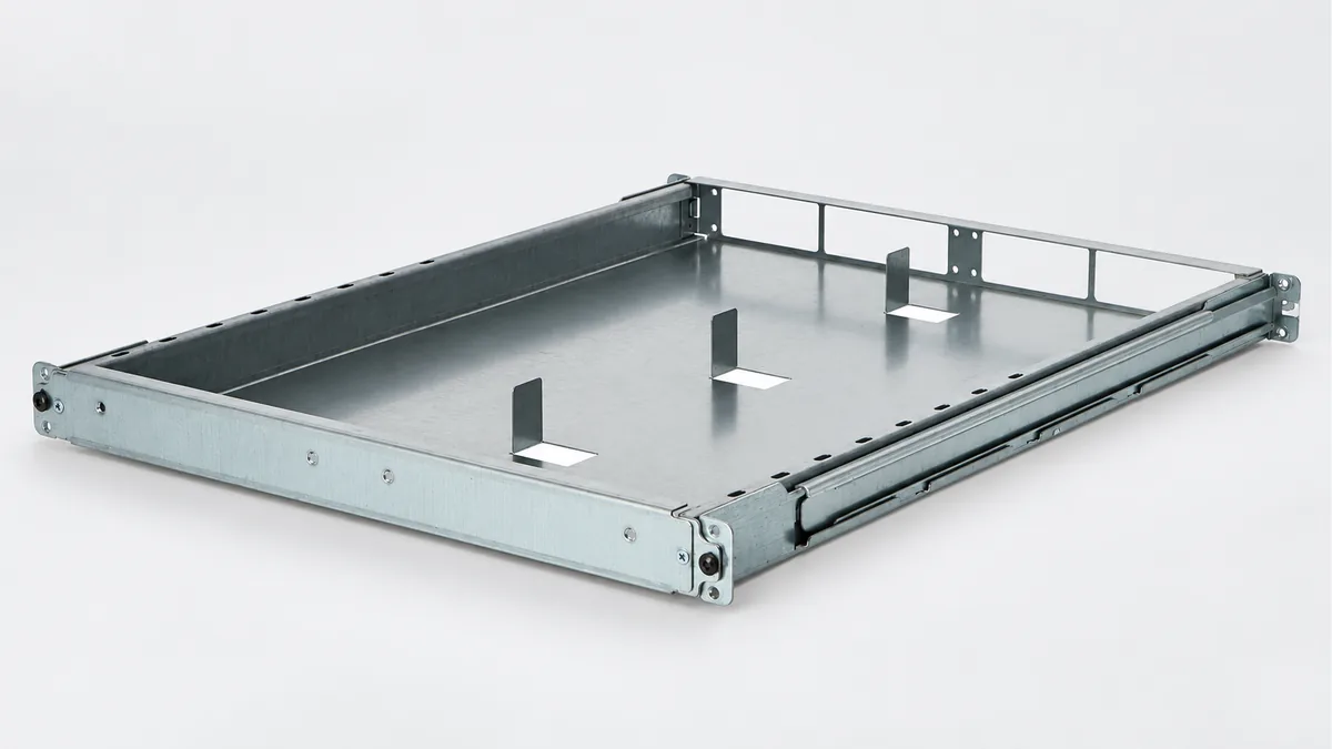
Power Module Carriers to your design
Source the metal carrier that supports a removable power module in your charging or data-center power equipment. REALJET makes the formed carrier to your module envelope, fixing details and service arrangement.
Choose the part and delivery condition
| Your order | Information that sets the scope |
|---|---|
| Individual formed carrier | Module envelope, carrier profile and apertures |
| Carrier with connection features | Support details and fastening positions |
| Carrier with specified hardware | Hardware list and required assembly state |
The metal carrier and listed hardware form the supply scope. Power modules, electrical connectors and controls are separate unless explicitly included.
Fit it to the equipment around it
Module insertion should reach the intended support and fixing points without the carrier obstructing the connector or removal tools. Show the insertion direction, connector approach and service clearance on the assembly drawing. EV charging and AI power applications require separate module interfaces.
| Intended installation | Equipment interface to supply |
|---|---|
| AI equipment | AI infrastructure modular power equipment |
| EV charging equipment | DC charging power cabinet |
Plan the manufacturing around these features
The steps below are proposed for the drawing review. Your material, geometry and acceptance requirements determine the final route, tooling and inspection provision.
Review entry and connector zones
Locate carrier supports and fixings relative to the insertion path. Resolve apertures close to bends before the blank is prepared.
Form the carrier
Plan the bend order to preserve access to inner supports. Add only the connections or reinforcement present in the component drawing.
Finish entry and locating edges
Review burr removal, finish allowance and hardware installation at module seats. Inspect locating features after finish where treatment affects fit.
Manufacturing capability for your component
| Your component feature | Existing process and its use | Confirm for your order |
|---|---|---|
| Carrier envelope | Plate preparation and CNC bending. Review bends and openings with the module insertion path before forming. | Small return tooling and the finished support height. |
| Fixing and support features | Deburring, component assembly and specified machining. Finish locating features and include only the hardware/connections identified in the carrier BOM. | Connector-zone clearance, hardware route and cabinet mating fixture. |
| Delivered entry edges | Surface-treatment routes. Review coating allowance and burr removal at module entry/locating edges. | Trial fitting with the nominated module and surrounding cabinet arrangement. |
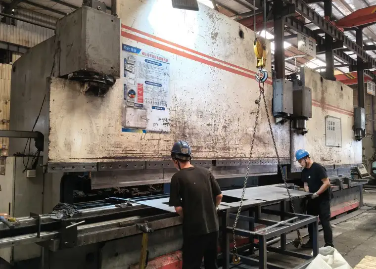
CNC bending is relevant to the carrier profile. The final module envelope and connector approach still need a carrier-specific fit check.
Define what the first article must demonstrate
| Feature | Proposed check | Record to agree |
|---|---|---|
| Module envelope and supports | Measure slot dimensions, support height and fixing pattern from the carrier datums. | Support/slot readings and datum setup. |
| Insertion and fixing | Use the specified module/dummy to check the insertion path, seating and fastener access; keep connector mating separate from structural alignment. | Insertion/fixing checklist and dummy revision. |
| Removal space | Check service removal with the surrounding cabinet arrangement represented; inspect entry edges for damage risks. | Removal observations and represented cabinet interfaces. |
Identify the drawing revision, measurement datums and pass/fail limits before the sample is made. The quote confirms the available measuring setup, any mating fixture and whether a specialist test needs an external provider.
Packing for your next assembly step
Protect entry edges and attachment tabs. Identify module variants by part number so similar carriers are not mixed during cabinet assembly. State the quantity and delivery city so packing volume and the requested delivery terms can be included.
Questions before you send drawings
Can a loose power module alone prove the carrier fits the cabinet?
It can check some module interfaces, but not the full installed access. The first-article plan should represent the cabinet or shelf attachment and service space as well as the module.
Can the carrier be made for our power module?
Yes. Send the module envelope, support and fixing details with the cabinet or shelf interface. Identify any connector zones that the metalwork must keep clear.
What should I send for the drawing review?
Send the dimensioned PDF, available STEP/DXF/DWG files and assembly view. Include material, finish, quantity, delivery city and drawing revision. Mark the features in the inspection plan that control acceptance.
Can we approve a sample before ordering repeat quantities?
Request a sample or pilot batch with the agreed dimensional report and any mating checks. Scope, timing and test provision are quoted after review; repeat supply follows the accepted drawing revision and any agreed sample changes.
Discuss your power module carrier
Send the part and assembly drawings with your quantity and required delivery condition. Highlight the interfaces and checks listed above that matter to your order.
Attach files in your email application. To arrange file transfer first, use the enquiry form.
AI server and data-center components → · Battery storage, EV charging and solar components →