
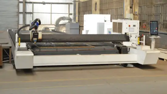
Where cut and formed parts sit in a machinery build
Not every bought-in component needs a machined bore or a ground face. Machine guards, brackets, cover plates, chute segments, ducting, tank shells, base plates and stiffener sets usually begin as flat plate or sheet, get cut to a blank, get formed to shape, and only then meet a welder or an assembly bench. Buyers often send them to a supplier under one enquiry even though the operations behind them behave differently. Cutting is a thermal process with defined quality classes. Forming is a cold process with radius and springback limits set by the material.
Realjet manufactures machinery components to customer drawings, and cut and formed parts are frequently the first stage of those packages. That means the enquiry runs on your drawing, your material grade and your inspection requirements, not on a catalogue shape.
Choosing the cutting route before you write the enquiry
Three thermal processes cover plate and sheet work, and each has a practical thickness window. ISO 9013:2017, the classification standard for thermal cuts, applies to oxyfuel cutting from 3 mm to 300 mm, plasma cutting from 0.5 mm to 150 mm and laser cutting from 0.5 mm to 32 mm. ISO published Amendment 1 to the standard in 2024, so the edition year belongs in the RFQ if cut quality is a contractual matter.
The choice normally follows thickness, material and the feature size on the part. Laser cutting suits thin and medium plate with tight contours and small holes. Plasma covers thicker plate and non-ferrous material, with a wider kerf and a rougher edge. Oxyfuel remains the economical route for the thickest carbon steel where edge appearance is not critical.
Decide who picks the process. If the drawing says "cut from 20 mm plate" and nothing more, the supplier selects the method, and the achievable edge quality follows that choice rather than your requirement.
Edge quality is a specification, not a default
ISO 9013 classifies a cut edge by two characteristic values: the perpendicularity or angularity tolerance u, and the mean height of the profile Rz5. Both grow with material thickness a. Perpendicularity ranges run from 0.05 + 0.003a mm at the tight end to 1.2 + 0.035a mm at the loosest, and roughness ranges from 10 + 0.6a µm to 110 + 1.8a µm. The standard's informative annex lists laser cutting as typically reaching limit deviation class 1, with oxyfuel and plasma at class 2.
A drawing can carry that requirement directly, in a designation such as ISO 9013-312:2017, which names the perpendicularity range, the roughness range and the dimensional tolerance class in one string. Most machinery drawings do not, and the omission is usually harmless until a cut edge is visible, is a sealing face, or becomes the start of a fatigue crack.
The same standard addresses parts that will be machined after cutting. Where a drawing does not say otherwise, it gives a machining allowance per cut face that rises with thickness, from 2 mm for workpieces between 2 mm and 20 mm thick up to 7 mm above 80 mm. If a machined boss or bearing face is going to be produced from a cut blank, the allowance and the stock condition should be agreed before the plate is cut, because a plate cut to the finished envelope has no material left to machine.
One practical test tells you where cut quality matters. Ask which edges will be welded, which will be machined, which will be painted over and which will be seen. A welded edge tolerates more dross than an exposed one, and paying for a tight cut class on an edge that disappears under a fillet weld buys nothing.
Forming limits the drawing has to respect
Press brake work has few universal rules, but the shop conventions behind them are stable enough to design around. Fabricators commonly apply a minimum inside bend radius close to one material thickness for mild steel, around 1.5 times thickness for stainless, and 1.5 to 2.5 times thickness for aluminium depending on temper, with the radius increasing as thickness grows. A press brake forming guide from a fabrication shop sets out the same conventions and the tooling constraints behind them (Designing for Press Brake Forming).
Two other limits show up on almost every formed part. A flange has to be long enough to sit on the die shoulders, which is why a minimum flange of roughly four times material thickness is a common shop figure. Holes and slots need clearance from the bend line, typically at least two times material thickness, or they deform into ovals when the material flows into the bend.
In air bending, the V-die opening sets the natural inside radius rather than the punch, and the radius falls somewhere near one sixth to one eighth of the die opening. Springback then pulls the angle back slightly after the punch withdraws. Mild steel springs back modestly, stainless and high-strength steel considerably more, and the amount grows with the bend radius and with thinner material. Shops compensate by overbending, which is why an angular tolerance stated on the drawing matters more than the radius value alone.
Rolling follows the same logic with an extra constraint. A cylindrical shell, a curved chute or a formed section has a minimum diameter the rolls can achieve in the plate thickness you have chosen, and the plate must be long enough to pass through the machine. If the part is a rolled shell that will later be welded into a larger assembly, say so, because the weld prep and the rolling direction are decided at the blank stage.
What the RFQ package should carry
A cut and formed enquiry that can be quoted without assumptions usually contains:
- the drawing set with revision status, and a clear statement of which dimensions are functional and which are reference;
- the material grade, thickness and the standard the mill certificate will be issued against, with the required material certificate and traceability level named;
- a decision on who develops the flat pattern, because bend allowance and K-factor assumptions sit with whoever owns the unfold;
- the cut quality class where it matters, and which surfaces will be machined afterwards;
- bend radii, flange lengths and angular tolerances for formed features, since a general tolerance block rarely says how a formed angle is measured;
- whether grain direction or rolling direction matters for structural or fatigue reasons;
- the edge condition after cutting, including deburring, radiused corners and weld preparation;
- quantities per part, spares and the delivery sequence, including whether parts ship as flat blanks, formed parts or finished with a coating system.
It also helps to name the project's steelwork execution standard where the parts feed a welded structure. A cut edge specification in that standard can be stricter than the default cut class, and discovering the difference after the plates are cut is expensive.
Inspection and evidence
Formed parts carry a tolerance stack that flat parts do not. A blank held to a tight tolerance loses part of that accuracy at the bend, and the loss grows with the number of bends. Inspection planning should therefore say what is measured on the blank, what is measured on the formed part and with what equipment: a dimensional report from the flat table, an angular check with a protractor gauge or a digital angle finder, a first article for the first part of each geometry.
If the part has any of these characteristics, a first article inspection with recorded measurements should be part of the order rather than a later addition: a visible face, a sealing or mating surface, a tight hole-to-bend relationship, or a geometry that sets up the downstream weld. Where a cut or formed part is welded afterwards, the welding procedure and NDT scope belongs in the same enquiry so the process sequence is reviewed once.
Where responsibility sits
The buyer owns design intent: material selection, functional dimensions, the standard that governs the edge or the formed feature, and the inspection level needed for the application. The manufacturer owns process selection within the stated requirements, tooling choice, forming sequence, in-process checks and the honest reporting of deviations before fabrication rather than after.
What a buyer should not accept is a silent change. If a shop decides that a specified radius is not achievable in the grade supplied, or that the cut class on a visible edge will not be met at the quoted price, that has to come back as a question. A deviation raised before cutting costs a drawing revision. The same deviation found at goods-in costs a rework job.
Preparing the enquiry
Before sending the package, confirm the drawing revision, the material and thickness, which edges matter, whether any surface will be machined after cutting, and how the formed features will be measured. With those points answered, a manufacturer can propose the cutting route, the forming approach and the inspection plan against your requirements rather than around them. Start with the contract manufacturing enquiry route and include the drawing set, quantities and the quality evidence you need, and the review can begin from a complete brief.