
Where the sealing decision becomes a mould decision
The water tightness of a single-shell segmental lining rests almost entirely on the joints between segments. Ribbon gaskets sit in grooves cast around the segment edges, and the seal works by compression: adjacent gaskets press against each other and against the concrete, so contact pressure has to hold along the whole profile against the design water pressure. The DAUB recommendations for the design, production and installation of segmental tunnel linings set out that relationship and the production tolerances that support it.
Those grooves are formed during casting, which places the mould in the middle of a sealing problem. If a groove sits out of position, runs too deep, or loses its shape at a corner, the gasket cannot develop the compression the tunnel designer assumed. That is why the joint face of a segment mould deserves its own specification, separate from ring geometry and segment families. The ring geometry and mould set guide covers the ring side of the same purchase.
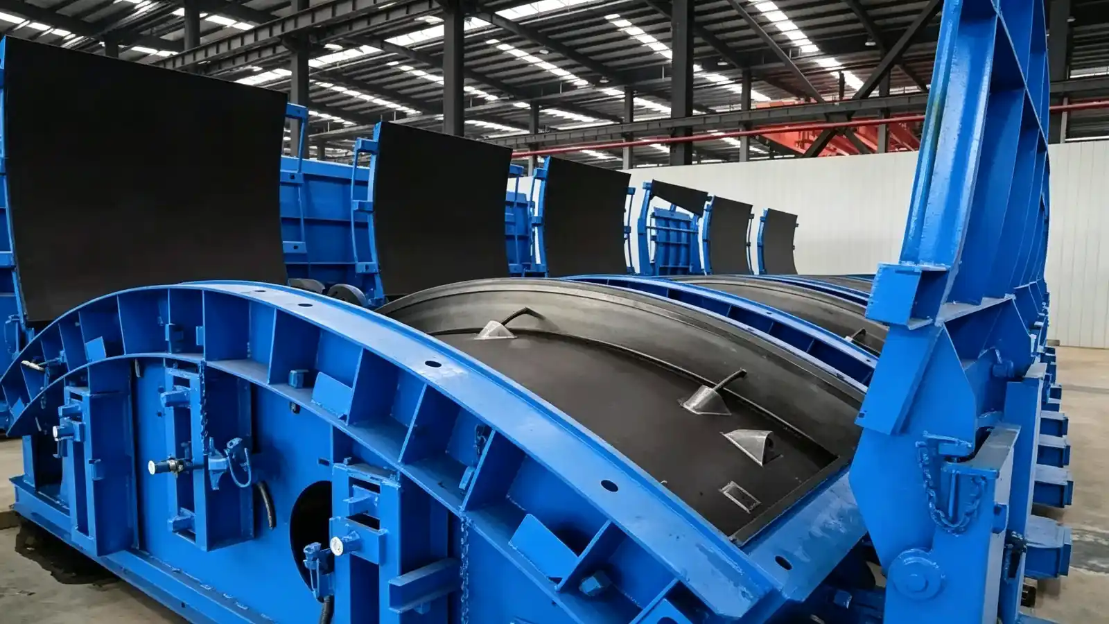
Realjet builds steel moulds through its precast concrete mould range. The relevant application family for this enquiry is tunnel and underground moulds, and the published tunnel lining segment mould page is the product reference to name in the RFQ.
What the buyer has to fix before the mould is detailed
The mould maker reproduces a groove; the tunnel designer and the gasket supplier define it. Three inputs come from outside the mould workshop and have to be frozen before fabrication starts:
- the gasket system and its profile, including corner geometry, issued as a controlled drawing by the gasket manufacturer;
- the design water pressure, the expected joint opening and offset, and the residual leakage rules for the tunnel;
- the joint layout, meaning the insertion guide or horn, bolt pockets, dowel holes and any caulking groove.
The ITA-AITES guidelines for the design of segmental tunnel linings treat gasket design and groove design as separate steps, with the required gap, offset and tolerances defined by the designer. Until those values exist in writing, a mould quotation is a guess about geometry.
A groove machined into the mould face or formed by a replaceable former
Two production routes are common, and the choice affects both first cost and the risk carried through the project.
Machining the groove directly into the mould plate keeps the geometry stable across every casting cycle. The trade-off is flexibility: if the gasket profile changes, or if a corner is damaged, the plate has to be re-machined or the joint face rebuilt, which is workshop work on a large component.
Forming the groove with a replaceable steel or polymer former lets the groove be changed without touching the main plate, and a worn section can be exchanged in the plant. The trade-off is that the former becomes a controlled item in its own right, with its own fixing method, a seal against concrete ingress behind it, and replacement stock held for the project.
Both routes require the same answer to one question in the RFQ: who confirms that the cast groove matches the gasket supplier's profile, and by what measurement.
The rest of the joint face
The groove is not the only feature formed on the joint face. Around it, the mould has to produce:
- the insertion guide, or horn, for the key segment;
- bolt pockets, channels or dowel holes, with tolerances that keep a ring assemblable;
- erector cone or lifting socket positions in the segment;
- chamfers and edge breaks that reduce chipping during ring building;
- any caulking groove outside the main gasket line.
DAUB lists separate manufacturing tolerances for these features, including ±1 mm for bolt pockets and channels and ±2 mm for erector cones, alongside a rectangularity deviation on the longitudinal joint of ±0.5 mm for rings up to 8.0 m internal diameter. The mould has to hold all of them at once on the same face.
Corners need attention during mould detailing. Restoring forces from the gasket concentrate at frame corners, and a corner former that lifts or shifts while a ring is being built removes compression exactly where water ingress tends to start. The RFQ should ask how corner geometry is located, fixed and checked.
Tolerances the mould has to hold
The tolerances that matter to a mould buyer are the ones the finished segment must meet, because the mould has to hold them while the concrete is still moving. DAUB's table for single-shell rings lists gasket groove width and depth at ±0.2 mm and the position of the gasket groove axis at ±1.0 mm. Evenness of the longitudinal and ring joint contact zones is listed at ±0.3 mm for rings up to 8.0 m and ±0.5 mm for the larger class.
Those figures describe the segment, so the mould needs a tighter working target in the workshop, an inspection method that can actually measure a groove, and a clear decision about what is measured on the mould and what is measured on a first cast segment. Groove width and depth are awkward features to verify once a mould is assembled, which argues for a first-article casting measured and documented before the mould is accepted.
Two further production points belong in the same conversation. Groove surfaces that contain rock pockets or voids reduce sealing capacity, so the mould face should be detailed to help concrete consolidate at the groove instead of trapping air. Groove edge distance from the segment surface affects whether concrete spalls near the groove under gasket restoring force, and it cannot be adjusted after the mould is built.
What to send with the mould RFQ
- approved segment drawings with ring and joint details, plus the segment schedule for the project;
- the gasket manufacturer's profile drawing, including corner details;
- joint hardware, meaning bolts, dowels and insertion guides with their tolerances;
- the tolerance table the mould will be measured against, with the standard edition named;
- the casting method and cycle, so the mould opens, cleans and resets in the plant's sequence;
- the acceptance evidence required, including dimensional records and first-article measurements;
- the design water pressure and joint opening, so the mould maker understands why the groove tolerances are set as they are.
Checking fit before fabrication
A short review before the mould goes to the workshop avoids most of the later argument. Confirm that the groove profile on the mould drawing matches the gasket manufacturer's current issue, that the corner details work with the ring assembly sequence, and that the tolerance table can be measured with equipment the inspector can access.
Where the joint system is still under review, the practical sequence is to freeze the gasket and joint design first, then release the mould for fabrication. Mould steel is easier to machine once than to correct after a thousand segments.