
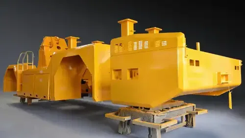
When the structure is larger than the shop and the road
A welded structure is usually drawn as one piece. On the shop floor it becomes a division problem, because a machine body, a press frame, a gantry or a heavy working platform may be larger than what one workshop can position, weld and machine in a single assembly, and larger than what the route to site will carry.
Two envelopes decide the answer, and neither is a matter of opinion. The first is the fabricator's own. Realjet's published manufacturing route covers plate cutting up to 12 m, press brakes with working lengths from 3,200 to 6,000 mm and capacity up to 500 tonnes, and a 12 m large-part painting line. Those figures describe the outer size of what the documented cutting, forming and finishing scope handles as a single piece. The second envelope is transport. On the United States National Network, vehicle width is limited to 102 inches (2.59 m) and gross vehicle weight on the Interstate System to 80,000 lb (36.3 t), with no federal height limit and state limits commonly between 13 ft 6 in and 14 ft 6 in, as set out in the Federal Highway Administration summary of truck size and weight limits. Loads beyond those limits need permits for every state on the route, and a wide or heavy load can be refused a route altogether.
A structure that crosses either envelope gets divided, and from that point the order is no longer only about fabrication. It is about where the division falls, how the pieces are joined, and how the finished geometry is proved.
Division is a design decision, not a workshop preference
Where a weldment is divided changes how it carries load. A division placed through the middle of a highly stressed member, or one that interrupts a fatigue-sensitive detail, is a change to the structure rather than a detail of manufacture, and it has to be approved by the party responsible for the design.
That distinction is worth stating plainly in the enquiry, because confusion here is expensive to unpick once the first pieces are welded. The buyer's engineer owns the structural consequence of the division. The fabricator can and should propose divisions that are practical to build, and should say what each one costs, but cannot become the designer of the joint by silence.
Practical divisions tend to share the same properties. They fall where the section is simple and repetitive, where there is room to weld and inspect the joint, where the joint can be welded in a position the procedure covers, and where each piece stays inside the handling, machining and coating envelope of the shop. A division that saves freight but puts a full penetration weld where nobody can reach it is not a saving.
How the pieces are joined sets the alignment problem
Once a structure has more than one piece, the finished geometry depends on how the pieces come together. Three arrangements cover most cases.
A bolted joint carries the geometry in the hole positions and their clearances, and it moves the alignment problem into the drilling, the faying surfaces and the possibility of reaming and pinning on site. A welded joint makes the geometry permanent at the moment of welding and depends on fit-up, access and the sequence, which is a different risk profile. A pinned or dowelled joint locates the pieces positively but has to be designed as such, and its holes are the tightest feature in the assembly.
Execution standards are the usual way to fix the rules. Steel structures in Europe are executed to EN 1090-2, which covers bolting as well as welding. Preloaded bolting assemblies are qualified as a set, bolt, nut and washer together, under EN 14399-1 so that they are not mixed between makers, while non-preloaded structural assemblies are covered by EN 15048. A buyer who intends to make the site joint with preloaded bolts should say so in the enquiry, because it changes the hole preparation, the surface condition and the tightening method that the fabricator has to allow for in the shop.
It also helps to keep two different numbers apart. Fabrication tolerance is what the shop can hold on a piece in its own setting. Alignment tolerance is what has to be true when the pieces are joined, and it is normally tighter than the sum of the fabrication tolerances would suggest. Asking for an alignment figure without saying where it is measured, or from which datum, leaves the fabricator to guess.
Tolerances worth naming: EN 1090-2 and ISO 13920
General tolerance references are often carried over from an older project without being re-read. Two of them do most of the work here.
EN 1090-2 separates essential tolerances, which protect mechanical resistance and stability, from functional tolerances, which protect fit-up and appearance. Functional tolerances are given in two classes, where class 1 is the routine default and class 2 requires more expensive measures through fabrication and erection. Projects may also add special tolerances for features the tables do not cover. The practical point for a buyer is that the class has a cost, and that it belongs in the enquiry rather than in a note exchanged after the first piece is welded.
Where distortion from welding dominates the shape, EN 1090-2 permits general tolerances for welded constructions to ISO 13920 as an alternative to its own functional tables. ISO 13920 works by class, from the tightest to the loosest, and separates linear and angular dimensions from shape tolerances such as flatness, straightness and parallelism. Class B is the usual production default. As an order of magnitude, a 3,000 mm dimension in that class is acceptable at roughly ±6 mm, which is worth knowing before a buyer assumes that an untoleranced drawing implies a close fit.
One more separation matters. Geometry and weld quality are governed by different standards, ISO 13920 for the finished shape and ISO 5817, or ISO 10042 for aluminium, for imperfections in the weld itself. Raising the weld quality class does not tighten the assembly dimension, and tightening the dimensional class does not improve the weld.
Trial assembly, match marking and the record
For a structure with site joints, the shop is the last place where a poor fit can be corrected cheaply. A trial assembly of the pieces before shipment shows whether the division works, and it converts an argument on site into a workshop task.
Three things make the trial assembly useful rather than decorative. The pieces must be assembled in the condition they will travel, with the coatings and the machined faces protected as agreed. The match marks must be applied where they survive handling, and must appear on the marking schedule as well as on the piece, so that the site team can match a physical mark to a document. And the record should state what was measured, with what instrument, against which datum, and what was corrected afterwards. A photograph of two pieces bolted together is not a record.
It is also worth fixing who pays if the site fit reveals a geometry problem, and whether the fabricator is expected to attend the first site connection.
Machining after the final joint
Welding moves the geometry that machining depends on, so the sequence matters more on a divided structure than on a single piece. Features whose position is only decided by the final assembly, such as bearing bores, seat faces, pivot holes and guideway mounting faces, are usually machined after the structure is together.
Realjet's machining and assembly scope covers drilling, boring, tapping, deburring and component assembly coordinated with fabricated datums, so critical holes, interfaces and final assembly dimensions can be held to one release. The limit is physical. A final assembly larger than the available machine envelope cannot be bored in one setting, and then the choice is between machining faces before assembly and controlling location through the joint, or planning a site machining operation with its own access, alignment and inspection requirements.
What to send with the enquiry
A fabricator can return comparable options when the enquiry carries:
- the overall envelope and the mass of each piece, with the centre of gravity where it is not obvious
- the transport limit that applies on the actual route, not a generic road or container figure
- crane capacity and access at both the loading and the receiving end
- whether divisions are permitted at all, and whether any location is excluded
- the joint type, and a statement of who designs it
- the alignment tolerance after re-assembly, with the datum and the measuring condition
- which features are to be machined after the final joint
- the evidence set required: piece dimensions, final assembly dimensions, weld records, material certificates
- how joint faces, machined faces and coatings are protected in transit
Protection and packing are a separate scope from the division itself, and the packaging and export scope note covers that part of the package. What matters here is that the enquiry states the division, because a supplier who receives one drawing with no division guidance will price the safest option it can imagine.
Decisions and who holds them
| Decision | Design engineer | Fabricator | Buyer and site team |
|---|---|---|---|
| Where the structure may be divided | Decides | Proposes practical options | Confirms against route and access |
| Joint type and its structural capacity | Decides | Details for fabrication | Installs to the agreed sequence |
| Tolerance class for the finished assembly | Specifies | Holds it in fabrication | Checks it on arrival |
| Trial assembly scope and record | Agrees | Performs and documents | Accepts before shipment |
| Features machined after the final joint | States the critical ones | Sequences and machines | Protects them on site |
Keeping design authority with the engineer and manufacturability with the fabricator is what makes the comparison between two quotations meaningful. Two suppliers who divide the same structure differently are not offering the same product, whatever the totals say.
Next step
The order of work is short. Confirm the transport envelope on the real route, decide with the engineer where the structure may be divided, choose the joint and its tolerance basis, and state which dimensions are proved before shipment. Then ask every bidder to return the same four things: the proposed division, the joint detail, the sequence for machining after assembly, and the evidence list.
Realjet builds custom machinery components and welded structures to customer drawings, coordinating cutting, forming, welding, machining, finishing and inspection within an agreed scope. Where a structure has to travel in pieces, the division, the joint and the acceptance criteria are confirmed in the approved project documents before manufacturing begins.