
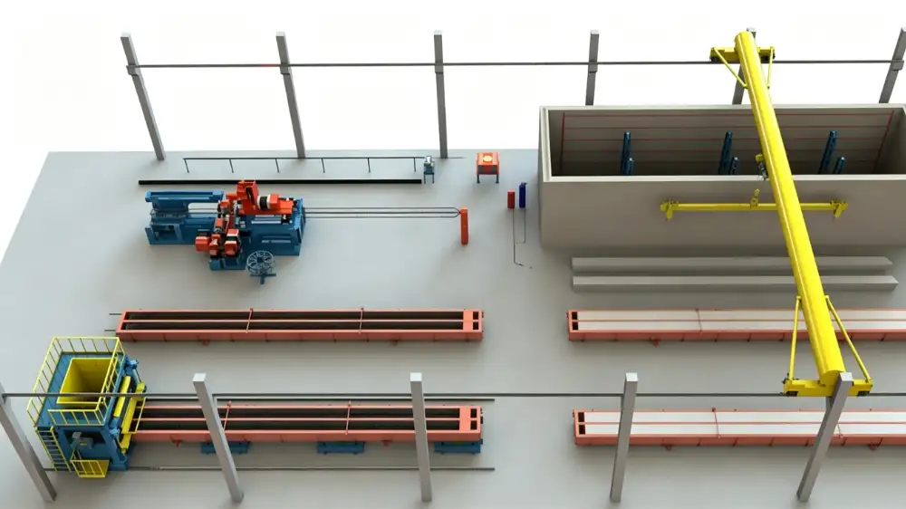
Why ground transfer needs three coordinated roles
Moving a long spun pile mould across the plant is not a single device job. The mould is carried on a trolley, pushed or pulled along a route, and positioned at each station. On most lines this involves three separate equipment items: the transfer trolley that carries the load, the friction-wheel drive that provides controlled motion, and the winch that supplies pulling force on routes where a driven wheel is not used.
Treating these as independent purchases is a common mistake. The trolley, the drive and the winch must be specified together, because each one assumes something about the others. The trolley frame decides the contact surface the drive pushes against. The drive assumes a trolley mass and a route. The winch assumes a rope path and a resistance to overcome. If one is changed after the others are ordered, the whole transfer system can fail to line up.
Route planning belongs to this same early step. Before any of the three is selected, map the path the mould takes from mould assembly through tensioning, spinning, curing and demoulding, and note where it must stop and hold position. That sequence is what the trolley, drive and winch are built to serve.
The transfer trolley carries the load
The transfer trolley supports the loaded mould, or in some layouts the finished piles, as it moves between production or finishing stations. Its frame, support spacing and contact surfaces are selected for the product mass, geometry and condition at the time of transfer.
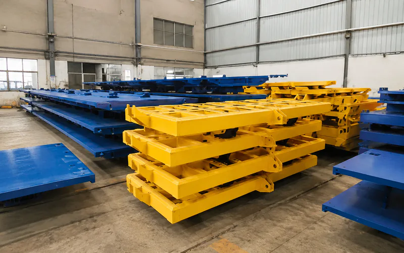
Transfer Trolley for Spun Concrete Piles
The transfer trolley supports the loaded mould or finished piles during movement between stations. Its load rating and support spacing must suit the heaviest item the range puts in motion.
View equipment detailsFor a mould-carrying trolley, the rated load must cover the heaviest mould in your range with its concrete and reinforcement, not just the empty shell. Support spacing should suit the mould length so the load is carried without excessive deflection. Note that a trolley intended to carry a complete steel mould is different from one sized for finished piles, and the two should be specified separately even when they share a travel route.
The friction-wheel drive provides controlled motion
The friction-wheel drive moves the trolley through contact with its drive interface. It transfers force to the trolley without lifting it, and it is the usual choice where you want powered, repeatable movement along a fixed path.
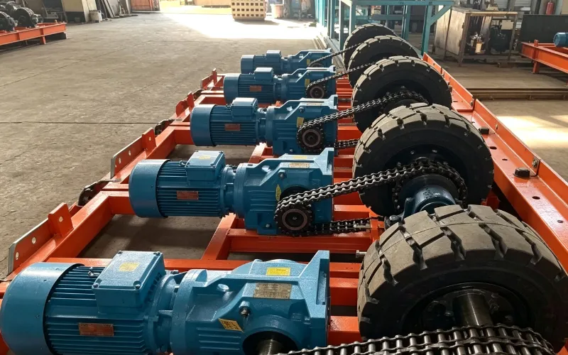
Friction-Wheel Drive for Production Trolleys
The friction-wheel drive moves the trolley along its route through contact with the trolley interface. Drive force, speed and stopping positions are set for the trolley load and line layout.
View equipment detailsThe drive and the trolley are separate items. The trolley frame, supports, wheels, travel path and contact surface must be reviewed together with the proposed drive. The number and location of drive units depend on the transfer route, the required driving force, the contact arrangement and the station spacing. Where trolleys move between shared work areas, positioning and stopping requirements also matter, so the drive control must match the stopping points in your layout.
Decide early which sections are driven and which are pulled. A continuously powered route favours friction-wheel drives placed at intervals, while a single long pull between two fixed points favours a winch. Mixing the two on one route is possible, but the control system must know where each method applies so the trolley stops at the right place.
The winch supplies pulling force on defined routes
A material transfer winch provides pulling force along an agreed route. It may serve a trolley or another defined transfer duty, with the rope path and anchoring coordinated to the plant layout.
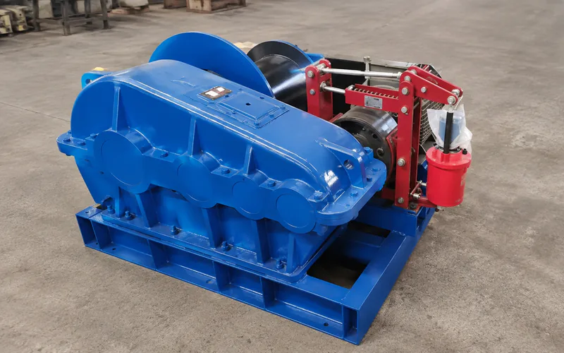
Winch for Spun Pile Plant Material Transfer
The winch supplies pulling force along a defined route where a motorised drive is not used. Line pull and rope routing depend on the moving load and the transfer distance.
View equipment detailsThis is a pulling application, not an overhead lifting one. Any lifting duty needs its own equipment selection with confirmed load, braking and operating requirements, and a pulling arrangement should not be assumed suitable for lifting. Line pull cannot be read from trolley mass alone: route gradients, rolling resistance, starting conditions and rope routing all affect the requirement. Provide the moving load and the route information together with the required speed and operating frequency.
Confirming the interfaces before purchase
Before you request quotations, capture the transfer parameters as a single package:
- The loaded mass of the heaviest item the trolley will carry, with its length and support points.
- The travel route, including gradients, turns, station positions and the distance between them.
- The required travel speed and the stopping accuracy at each station.
- Whether motion is by friction-wheel drive, winch, or a mix of both along different sections.
- The rope routing and anchoring details if a winch is part of the system.
Position feedback and stopping accuracy deserve specific attention. The trolley must stop within tolerance at each station so the crane and the spinning equipment can engage. Confirm how position is sensed, whether stops are mechanical or controlled, and what happens on a power loss. These details decide whether the transfer system integrates cleanly with the rest of the line rather than becoming a manual bottleneck between stations.
Realjet supplies spun pile production lines and individual handling equipment, and we do not sell finished spun piles. Share your layout, the heaviest mould in your range and the station sequence, and we will help you coordinate the trolley, drive and winch so the ground transfer matches the rest of the line. You can compare the full spun pile production line scope before you send an enquiry.