
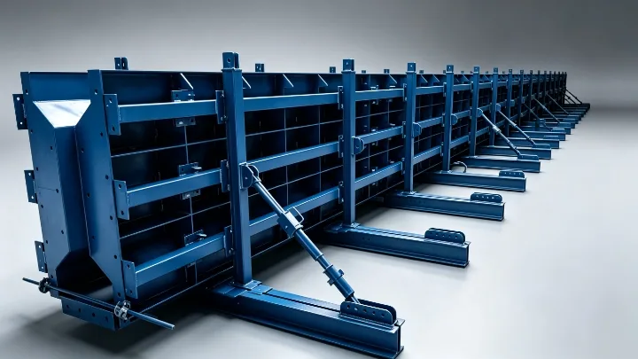
The end form is where the girder design meets the mould
An I-girder mould is usually described by its section and its length. The end forms attract less attention, yet they are the part of the mould that has to agree with the prestressing system, and the part most often left to the supplier to interpret.
On a pretensioned girder the strands run along the bed and pass through the end form at each end of the component. The form closes the mould, shapes the end face of the girder, and carries the holes the strands pass through. On a post-tensioned girder the same component holds the duct and anchorage positions instead. Either way it is a plate assembly whose hole pattern has to match a drawing prepared by the designer, and whose position has to hold through repeated casting cycles.
The bridge and transportation moulds family covers the girder mould systems used for this work, and the I-girder moulds product page sets out the design basis for this component type, which begins with the approved flange and web geometry, the girder family, the prestressing details and the production method.
What the strand pattern asks of the end form
The strand pattern is a designer's output, not a mould supplier's choice. It fixes how many strands there are, of what size, and where they sit in the section. Common strand sizes in bridge work are the nominal 12.7 mm and 15.2 mm diameters, supplied to standards such as ASTM A416 or EN 10138-3, and those are the sizes the strand bond requirements recognised in plant quality control refer to.
The end form then has to do three things with that pattern. It has to place a hole at each strand position, sized to let the strand pass without binding while keeping the grout or concrete loss at the end face acceptable. It has to hold the relative position of those holes to a tolerance the design can accept, because every hole is a strand, and a strand that sits outside its design position changes the prestress geometry of the whole girder. And it has to keep the end face square to the girder axis, since for many girders that face is a bearing surface when the unit lands on its supports.
Suppliers are not in a position to derive this pattern, and should not be asked to. The useful enquiry states the approved strand layout and the tolerance the project applies to it.
Debonding changes the pattern locally
Debonding is the practice of leaving selected strands unbonded over a length at the girder end to reduce the stresses transferred there. It is common in pretensioned I-girders, and it is regulated. AASHTO LRFD bridge design specifications limit how many strands may be debonded, require debonded strands to be distributed symmetrically about the member centreline, and set minimum spacing between termination points, with the current rules tracing back to the NCHRP Project 12-91 research on strand debonding for pretensioned girders, summarised in the AASHTO LRFD changes reported in ASPIRE.
For the mould this matters in a concrete way. A debonded strand is still a strand, and it still passes through the end region. The debond is created by a sleeve or a similar de-bonding device that separates the strand from the concrete over a set length, and the end form is where that device starts. The practical questions for the mould supplier are therefore whether the sleeve is positioned by the end form or simply threaded over the strand in the mould, whether the debonded positions are plugged after stripping, and whether the debonding schedule is the same on every girder the mould will cast.
That last question decides whether the mould carries one fixed end pattern or an assembly of replaceable inserts. The I-girder moulds product page describes replaceable end details and inserts as a configuration applied where an approved component family permits adjustment, and this is the case that makes them worth the extra fabrication.
One mould, several girder variants
It is unusual for a project to need a single girder. Bridge schemes commonly use a family of sections, and the end details change within that family: different strand counts, different debonding lengths, sometimes different end block dimensions.
Two routes are available, and they cost differently. A single interchangeable end assembly with inserts for each variant keeps one mould working across the family and reduces the number of moulds in the yard, at the price of more engineering in the form itself, more parts to track and more changeover time between castings. Separate end forms or separate moulds remove the changeover and simplify the records, at a higher first cost and a larger footprint.
The comparison only works if the enquiry states the variant list and the casting sequence. A supplier asked to price a mould without them will price the simplest case and leave the changeover to be discovered on site.
Tolerances, the datum, and what the end form has to hold
Product tolerances for precast bridge elements come from the project and from the standard it names, which in Europe may be EN 15050 for precast concrete bridge elements and in North America the PCI tolerance documents that plants work to. Whichever applies, the mould has to be built tighter than the product, because casting and handling consume part of the allowance.
Three dimensions deserve to be named separately in the enquiry rather than left inside a general note:
- the girder length between end faces, and the tolerance on it, since this sets bearing positions at both ends
- the squareness of each end face to the longitudinal axis
- the position of every strand hole, both relative to the section and relative to the other holes
It also helps to state the reference condition for measurement, whether the check is made on the mould before casting, on the first girder after stripping, or on both. A mould that is checked once at the works and never again will drift, and the drift shows up as a girder that no longer fits the bearing.
Release, stripping and access at the ends
The end regions of a pretensioned girder are congested. End block reinforcement, confinement steel, lifting anchors and the strand pattern all compete for the same volume, and the end form is the boundary of that congested space. Two mould decisions follow.
The first is access. If the end form is a closed plate with a full ring of strands, the placing and consolidation of concrete behind it has to be planned deliberately, and the form should allow whatever access the casting method needs.
The second is the release method. Plant practice for transferring prestress varies, and PCI MNL-116 records both gradual release of the jacks and heat cutting of the strands as accepted methods, with the plant procedure for a given strand size, mix and product governing the sequence. The mould end detail has to allow that sequence without trapping a strand or damaging the end face, and the detensioning method belongs in the enquiry because it changes what the fabricator allows around the strand holes.
One further interface is worth knowing about. Where the strands are anchored to abutments that are independent of the mould, the tensioning record has to correct for any temperature difference between the strand at stressing and the concrete at casting, and PCI quality control guidance flags this correction above a difference of about 15 °C. That is a reminder that the bed arrangement around the mould is part of the mould's design input, not something settled later.
What to send with the mould enquiry
The strand pattern above all, then the details that surround it:
- the approved girder sections, with the girder family and its variant list
- the strand size, type and the standard it is supplied to
- the strand pattern for every variant, with the positions of debonded strands and the devices used
- the debonding schedule and the tolerance the project applies to strand position
- the end face requirements, including bearing details and any anchorage or duct positions for post-tensioned girders
- the release strength and the detensioning method the plant intends to use
- the casting bed or abutment arrangement, and whether strands anchor to the mould or to the bed
- the target output and the changeover time available between variants
- the product tolerance standard the project names, and the reference condition for checking
The wider package around the mould, including the casting arrangement and the prestressing equipment it has to work with, is covered in the prestressing RFQ note and in the I-girder mould note on multiple sections.
Decisions and who holds them
| Decision | Design engineer | Mould supplier | Producer |
|---|---|---|---|
| Strand pattern and debonding schedule | Defines | Forms the holes and inserts to it | Places the strands and sleeves |
| Hole position and end face tolerance | Sets the project tolerance | Holds it in fabrication | Verifies on the first girder |
| Variant strategy, fixed or replaceable ends | Agrees the family | Engineers the inserts | Manages changeover |
| Release strength and detensioning method | States the design requirement | Allows for the sequence | Executes and records |
| Bed and abutment interfaces | States the bed arrangement | Matches it in the mould design | Maintains the bed |
Keeping the prestress design with the engineer and the forming detail with the mould supplier is what makes two quotations comparable. A supplier who is asked to design the strand pattern is being asked to take a responsibility the enquiry never assigned.
Next step
Collect the strand pattern, the debonding schedule and the release method before the enquiry goes out, then add the variant list and the tolerance the project applies to the end face. Those four answers decide whether the mould needs fixed ends or replaceable inserts, how many end assemblies are built, and what the first casting is checked against.
Realjet engineers project-specific steel moulds for I-girders around the approved section, girder family, prestressing details and production method, connecting process review, mechanical design, steel fabrication, assembly and inspection within the agreed scope. The mould is reviewed against the precast production line programme it has to fit, and final dimensions and interfaces are confirmed in the approved project documents before manufacturing.