
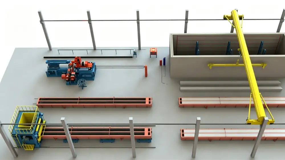
Start with the mould circulation path, not the machine list
A spun pile line is a circulation system first and a set of machines second. The product moves through reinforcement preparation, cage welding, mould assembly and closing, concrete batching and feeding, pretensioning, centrifugal spinning, steam curing, demoulding and handling. Each step needs a station, and those stations need a path a long mould can travel without a blind turn. Before you fix any equipment size, draw the movement of the mould from the closing station to the spinner, then to the curing pit, then back for demoulding. That path, not a catalogue of machine names, should drive the building footprint.
The buyer owns the pile drawings, the applicable standard and the concrete design. The line supplier works inside those inputs. In China the product is covered by GB/T 13476-2023, "Pretensioned spun concrete piles", which took effect on 1 March 2024 and replaced GB/T 13476-2009. It classifies piles by concrete strength, outer diameter, wall thickness and prestress category, and it sets the centrifugal casting and steam-curing regime. Other markets may apply regional equivalents such as EN 12794 for precast foundation piles. State the standard and the product mix before any layout discussion, because diameter range and pile length change both the mould length and the space each mould occupies.
Building span and crane coverage for long moulds
Spun pile moulds are long and rigid, and they are moved as complete assemblies. A crane must lift a loaded mould at two defined points so the member is supported along its length rather than bent at one hook. The bay span, the available headroom, the required lift height and the runway information decide whether one crane can serve every station or the line needs two bays.
When you brief the crane scope, give the loaded mould mass, the mould lifting-point drawings, the building dimensions and the stations to be served. Equal weight on the two hooks should not be assumed. The centre of gravity and the lifting-point arrangement set the load at each hook, and the crane selection must follow the agreed lifting plan. If the crane coverage stops short of the curing area or the demoulding bay, the line develops a manual bottleneck that no amount of spinning capacity will fix.
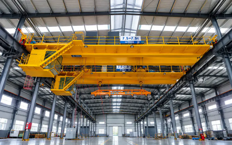
Twin-Hook Overhead Crane for Spun Pile Moulds
Long moulds are lifted at two defined points, so the twin-hook overhead crane and its runway must reach every station where a mould is loaded or moved.
View equipment detailsGround bearing and the track for internal transfer
The internal transfer route carries long, heavy loads across the production floor. A transfer trolley supports a loaded mould or a set of finished piles as it moves between stations, and the floor beneath it must carry that load without settlement that throws the track out of level. Long moulds are sensitive to twist, so a track that drifts even a few millimetres over its length can make mould alignment at the spinner and the curing pit difficult.
Confirm the soil condition and the finished floor specification before the layout is locked. The trolley rated load, the pile or mould length range, the support spacing and the contact arrangement are set by the product mass and geometry, while the travel route and the receiving stations decide the travel and positioning needs. If the ground preparation is treated as a generic slab, the later track correction is expensive and disruptive.
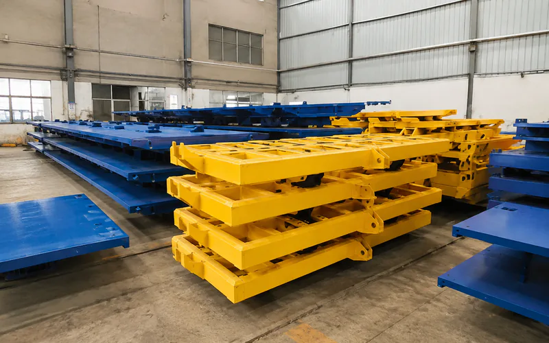
Transfer Trolley for Spun Concrete Piles
The transfer trolley carries loaded moulds or finished piles between stations, so its rated load and travel route set the circulation width of the plant.
View equipment detailsDriving the trolley along the transfer route
The trolley and its drive are separate equipment items. A friction-wheel drive moves the trolley by contact with its drive interface, and the contact surface, the supported load and the travel route must be reviewed together. The drive transfers force through contact, so the trolley frame, its wheels, the travel path and the contact surface cannot be specified in isolation.
Set the driving force, the travel speed and the stopping points from the loaded mass, the route gradients and the station spacing. Where trolleys share a work area or cross a station entrance, position sensing and controlled stopping matter more than raw speed. Review the drive placement and the number of drive units as part of the same layout exercise, not as a bolt-on after the track is poured.
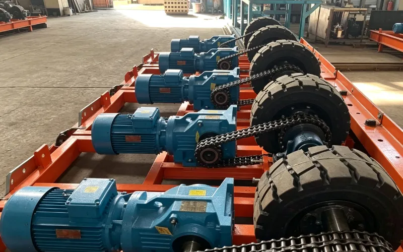
Friction-Wheel Drive for Production Trolleys
A friction-wheel drive moves the production trolley along the ground route, so its force and stopping points must match the trolley load and station spacing.
View equipment detailsReserve the curing volume and the boiler location
The curing chamber or pit is often the largest single item in a spun pile line and frequently the longest lead component. Its dimensions, door arrangement and position relative to the spinning and demoulding stations decide how many moulds cure at once, and that number often controls daily output more than the spinner count. Confirm the curing volume and the handling route to it before the building columns are set, because moving a curing pit later means moving the structural grid.
The steam boiler also needs a permitted location with fuel or utility supply, and it sits outside the equipment footprint in most contracts. Plan its flue, its water treatment and its safe separation from the production floor at the same time as the curing volume, not after the machines are ordered.
What to send the supplier for a layout review
A layout review works best when the supplier receives a comparable package. Send the pile diameter and length range, wall thickness, prestress level, target concrete strength, daily output and the applicable standard. Include a scaled building and equipment drawing, the available utilities, the ground condition report and the mould quantities and masses you already hold.
With those inputs, review the spun pile production line planning page so the response addresses the correct equipment boundary for your site. Share the product drawings and the site constraints early, and treat the first layout proposal as the start of a scope discussion rather than a fixed answer.