
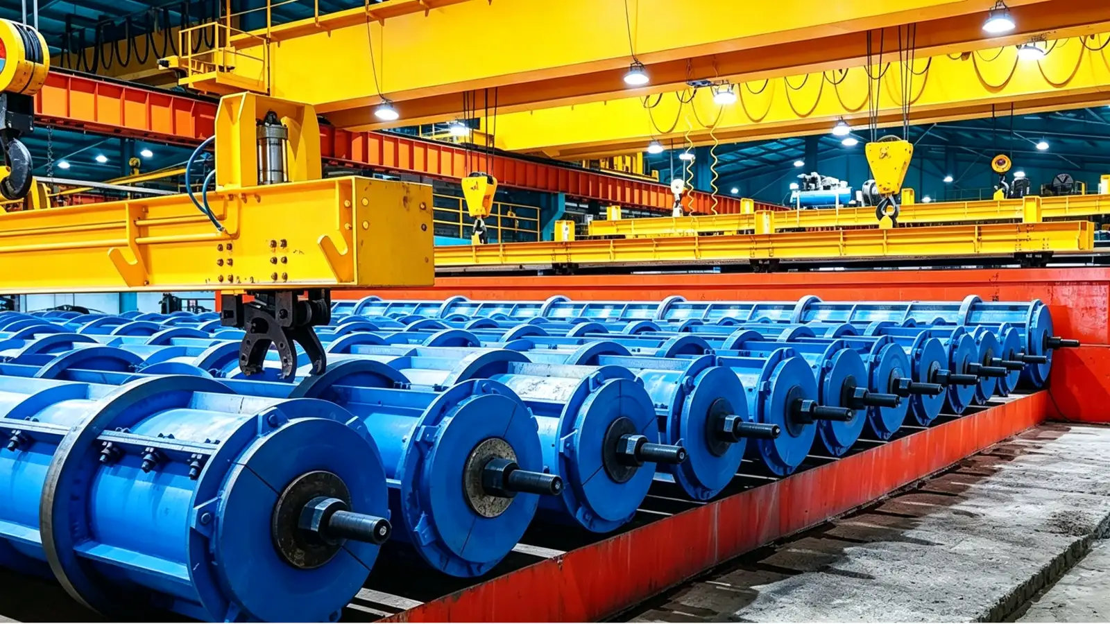
The cage is built before the mould is closed
A spun pile cage is a cylinder of longitudinal bars with a spiral wire welded to them. It is assembled before the cage is placed in the mould, the ends are fitted with the anchorage assembly, and the whole cage is tensioned later as part of the prestressing step. The cage geometry must fit the mould bore and the downstream tensioning and end-plate interfaces, so the preparation chain is a sequence with hand-off points rather than three separate machines bought independently.
The reinforcement design fixes the cage diameter, the longitudinal bar count and sizes, the spiral-wire specification and the pitch schedule. The preparation chain should be scoped to those drawings and to the daily cage demand, because a cage welding machine that outruns or lags the bar and wire supply simply creates a different bottleneck. The product itself is defined by the applicable standard, such as GB/T 13476-2023, "Pretensioned spun concrete piles", in China or EN 12794 for precast foundation piles in European markets, and the cage is one expression of that standard on the factory floor.
Cutting and heading the prestressing bars
The PC bar processing machine cuts the prestressing bars to length and forms the anchorage heads used in the spun pile reinforcement. Cutting length and head geometry must be coordinated with the cage and end-plate drawings, because the prepared bar has to land on the correct cage position and engage the mould-end anchorage without a field modification.
The incoming material and the finished head are the two inputs that decide the tooling. Bar diameter and material grade set the cutting and heading method, and the head geometry is tied to the anchorage detail rather than to the bar diameter alone. Confirm whether the equipment scope covers cutting and heading together or only one of them, and decide the incoming material handling, straightening and collection separately so the package matches the form in which bars arrive at the plant.
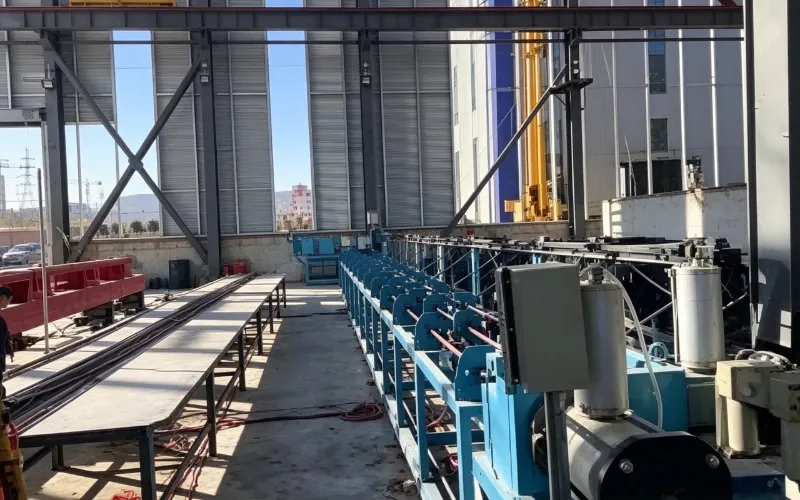
PC Bar Cutting and Heading Machine for Spun Piles
The PC bar processing machine cuts bars to length and forms the anchorage heads, so its output must match the cage length and the mould-end anchorage.
View equipment detailsDrawing the spiral wire to the finished diameter
The spiral wire that the cage welding machine lays onto the longitudinal bars is often supplied drawn to the finished diameter. A wire drawing machine prepares that wire from an incoming coil, reducing it to the diameter and condition the reinforcement design requires. Not every plant needs on-site drawing. A plant that buys wire already at the finished diameter and condition may not need the process at all.
Compare purchased-wire availability against your production demand, your material controls and the space the drawing process needs. Where drawing is justified, match the incoming and finished diameters, the coil sizes, the downstream demand and the available workshop space. The finished coil format must also suit the pay-off arrangement of the cage welding machine, because a coil that does not feed cleanly stalls the welding line regardless of the wire quality.
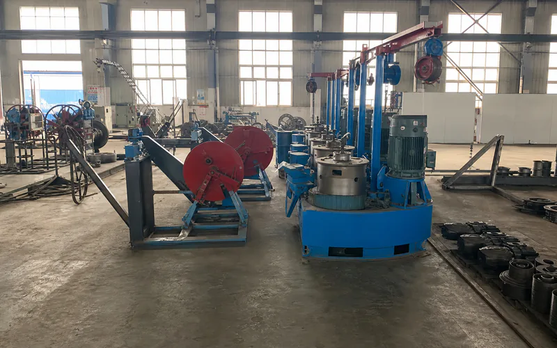
Wire Drawing Machine for Spun Pile Cage Wire
The wire drawing machine prepares the spiral wire to the finished diameter, so its output must suit the cage welding pay-off and the reinforcement design.
View equipment detailsWelding the cage to the pile drawing
The cage welding machine positions the longitudinal reinforcement and welds the spiral wire to form the cylindrical cage. Cage diameter and usable production length, longitudinal bar count and positioning, spiral pitch and wire feed, and the welding setup and discharge supports are the parameters that decide whether the cage fits the mould and the production rate.
Provide the cage diameter and length, the longitudinal bar count and sizes, the spiral-wire specification and pitch schedule, and the cage families that will share the machine. State which cage families share the tooling so that changeovers and the discharge arrangement can be reviewed. The cage does not apply prestress. That happens later at the tensioning stage through the approved anchorage and mould-end arrangement, so the cage geometry must leave room for those downstream interfaces.
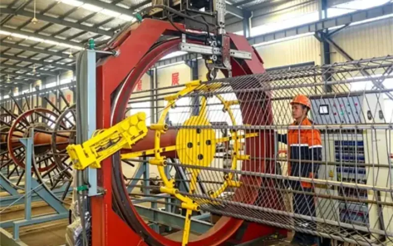
Cage Welding Machine for Spun Concrete Piles
The cage welding machine forms the cylindrical cage, so its diameter, length and spiral pitch must follow the pile reinforcement drawing.
View equipment detailsHand-off points to confirm before you buy
The chain works only if the hand-offs line up. The bar processing output must match the cage length and the mould-end anchorage. The drawn wire must suit the cage welding pay-off and the reinforcement design. The cage welding output must match the mould bore and the downstream tensioning and end-plate interfaces. Confirm these three connections as one package rather than buying each machine to its own separate specification.
Send the cage drawings, the bar and wire specifications, the spiral pitch schedule, the cage lengths and the required output to the supplier. With those inputs, review the spun pile production line planning page so the proposal covers the preparation chain as a connected system. Share the reinforcement drawings early and treat the first offer as the start of a scope discussion.
Keep the three scopes coordinated
Each machine in the chain has its own selection inputs, but the boundary between them is where projects go wrong. The bar processing scope, the wire drawing scope and the cage welding scope should be reviewed together so that throughput, coil format and discharge all meet at the same station. Civil works, local permits and the casting of the piles themselves sit outside the equipment supply unless the contract includes them, and the buyer still owns the pile design and the release approval. A coordinated equipment package that treats the three machines as one feeding sequence is easier to commission than three machines that each perform well in isolation.