
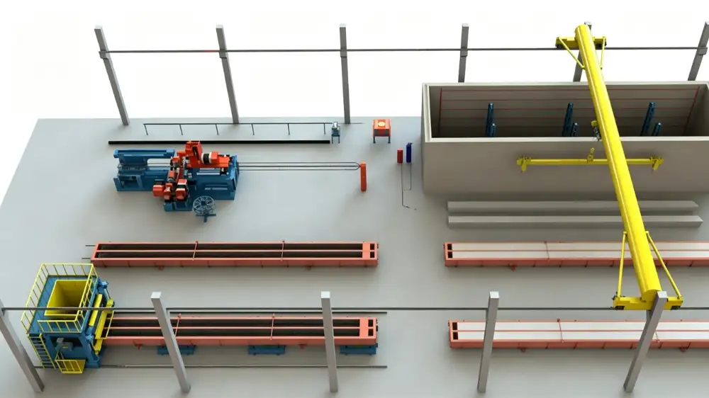
One mould circuit links the stations
A spun pile mould travels a full circuit on every cycle: it is opened and cleaned after demoulding, closed around a cage and end plates, filled and tensioned, spun, and then lifted into curing. Three handling tasks repeat through that circuit, and each one connects two different pieces of equipment: the fastening work at the mould flange, the two-point lift of the long mould, and the supported movement of piles between stations.
These tasks rarely appear as line items in a budget the way the spinning machine does. They surface instead as slow cycles, damaged pile ends and unsafe workarounds, which is why they deserve the same pre-order attention as the primary machines. GB/T 13476-2023 covers the marking, storage, lifting and transport of finished piles, and the handling equipment you buy has to serve that requirement from the first day.
Fastener work repeats on every cycle
Every split mould closes and opens on flange fasteners, and the work repeats for every pile. The practical questions are access and pace. Socket fit has to match the fastener sizes on the mould flange, the tool must reach along the flange without repositioning the mould, and the air supply at the station must hold pressure while the wrench works.
An impact wrench loosens and runs fasteners quickly, but it does not verify a specified final tightening value by itself. Where the mould procedure calls for a controlled final value, the fastening method needs a verification step, and that step belongs in the work instructions rather than in the tool specification. Provide the fastener sizes, the flange layout and the operating frequency in the enquiry so the tool, its air supply and the station arrangement are proposed together.
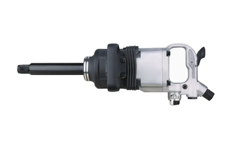
Pneumatic Impact Wrench for Spun Pile Moulds
Mould fasteners are opened and closed at every cycle, so the wrench must match the fastener sizes, the flange access and the compressed air available at the stations.
View equipment detailsTwo-point lifting of long moulds
Long moulds cannot be lifted safely from one point. A twin-hook overhead crane supports the mould at two coordinated points, and the load at each hook follows the mould's centre of gravity and lifting-point arrangement. Dividing the total mould weight by two is not a calculation; the lifting plan for the mould defines the loads, and the crane selection must follow it.
Coverage is the second half of the specification. The crane has to reach every station the mould must visit, from the demoulding position to the spinning machine and the curing pit entrance, and the bay span, lifting height and runway decide whether that path is clear. Provide the loaded mould mass, the lifting-point drawings and the building dimensions before crane selection, and confirm that the hook spacing works with the mould's lifting points across the whole movement.
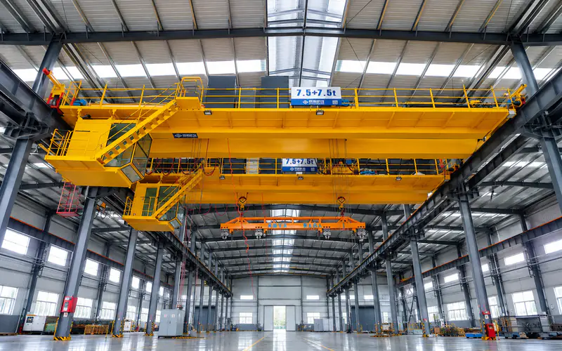
Twin-Hook Overhead Crane for Spun Pile Moulds
Long moulds are lifted at two coordinated points, so crane capacity, hook spacing and bay coverage must follow the mould lifting plan rather than a single rated load.
View equipment detailsMoving piles between and after stations
Once a pile leaves its mould, it is handled on supports that hold it at defined points. The transfer trolley carries piles between production and finishing stations, and its frame, support spacing and contact surfaces must suit the pile geometry and its condition at the moment of transfer. A long pile supported at the wrong points can crack under its own weight, and the damage appears after curing, when the pile is already a finished product.
The trolley also has to fit the plant's circulation plan: its travel route, positioning at the receiving station and drive or towing arrangement all follow the layout. Specify the pile sizes and mass, the number of piles per transfer and the route, and keep pile transfer separate from mould transfer even where the two share a track, because the support and load interfaces differ.
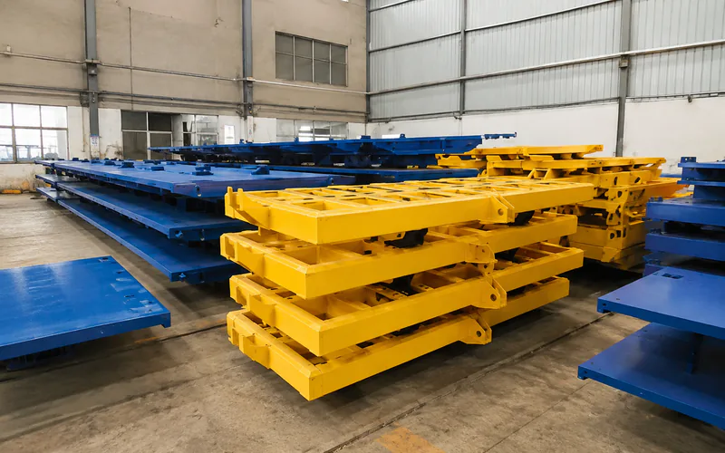
Transfer Trolley for Spun Concrete Piles
Piles leave the mould supported at defined points, so trolley load rating, support spacing and the travel route decide whether finished piles move without damage.
View equipment detailsConditions to confirm across the three interfaces
The three handling tasks share one condition: each one connects equipment from different parts of the scope. The wrench depends on the compressed air system; the crane depends on the building and the mould lifting points; the trolley depends on the routes and the receiving stations. None of these conditions is visible in an equipment quotation on its own, so each should be named in the scope discussion.
Confirm four things before ordering: the fastener sizes and air supply at the mould stations, the lifting plan and building dimensions for the crane, the pile support requirements and routes for the trolley, and which party supplies each interface item. Realjet includes the pneumatic tool, crane and transfer equipment in coordinated spun pile line packages and confirms these interfaces against the project requirements before a proposal is finalised.
Prepare the handling inputs with your enquiry
Send the mould fastener details, the loaded mould mass with lifting-point drawings, the bay and building dimensions, the pile sizes and the transfer routes. The spun pile production line planning page sets out the full equipment scope these items feed into. Handling equipment chosen with the same care as the primary machines is what keeps the mould circuit moving at the pace the line plan assumes.