
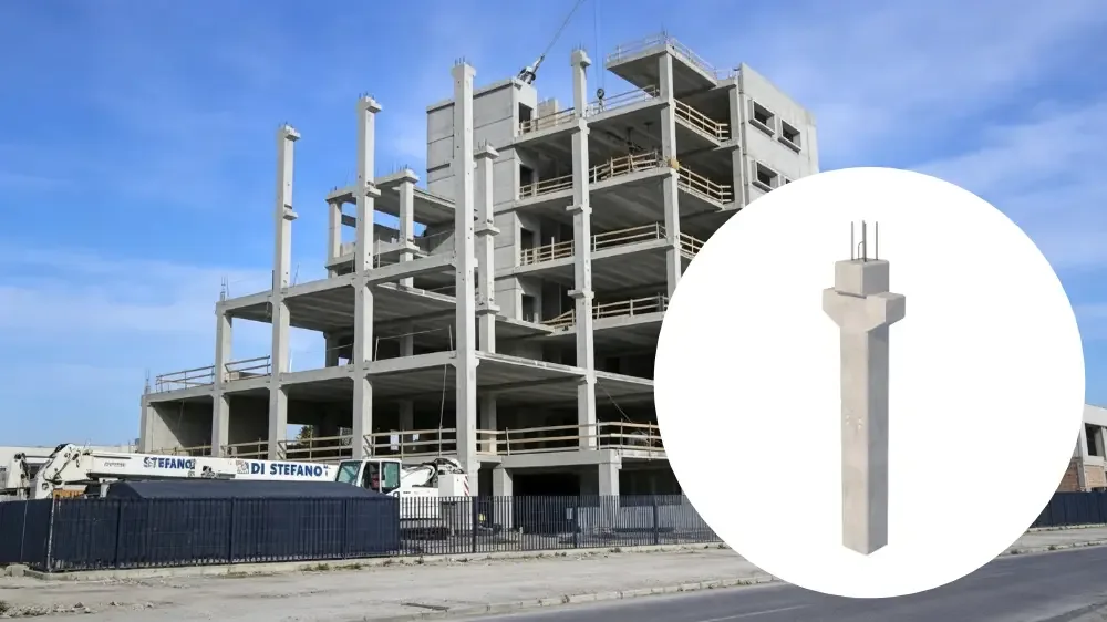
Why corbels belong in the mould discussion
A corbel is the short bracket that projects from a column face and carries the bearing end of a beam or a slab unit. Its shear span is short in relation to its depth, so ordinary beam design does not describe how it behaves. Codes treat it as a discontinuity region instead. ACI 318-19 devotes Section 16.5 to brackets and corbels, limits the shear span to effective depth ratio to 1.0 for that method to apply, requires the depth at the outer edge of the bearing area to be at least half the effective depth, and checks the horizontal restraint force at the bearing separately from the vertical load. Chapter 23 of the same code covers the strut and tie method that sits underneath the design.
None of that is a mould problem on its own. It becomes one because the corbel is cast into the column, so every geometric feature the designer relies on has to be formed, released and measured inside the mould. A bearing level that varies between columns, a tie bar that cannot be placed where the design assumes it, or an embedded plate that finishes outside its tolerance all start as forming decisions.
This article covers what the mould drawing has to fix. Realjet manufactures precast concrete moulds to approved drawings and does not sell columns or other precast components. Column geometry, reinforcement and connection design remain the buyer's design responsibility, set by the project documents and the code that applies.
Features that have to appear on the mould drawing
A structural drawing normally shows a corbel as an outline with reinforcement. The mould drawing needs more than that:
- the corbel soffit and top levels, dimensioned from the column's own datum rather than from the end of the mould;
- the corbel projection and width, the bearing area, and any recess that receives a bearing pad or a levelling shim;
- chamfers, fillets and edge breaks, and a statement of which corbel faces are exposed;
- the tie bars projecting from the corbel face, with position, spacing, diameter and the tolerance on the projecting length;
- any transverse anchor bar welded across the tie bars, because it sits close to the front face and can interfere with the forming arrangement;
- embedded plates, weld plates, shear plates or cast in sockets, with the face they finish flush to and the tolerance on position and level;
- shear keys, notches or recesses formed in the corbel top surface;
- lifting and erection provisions where the corbel is also a handling point;
- the visible face class for each surface, so the mould face material and finish can be matched to it.
The corbel schedule across the column family matters as much as the single detail. In a multi storey building it is common to find one column section with corbels at two levels, corbels on two or four faces, and a second column type carrying the same corbel at a different height. Each variation is a mould decision, and it is cheaper to decide them together than one at a time.
Forming a corbel: fixed box, removable former or adjustment
Because the corbel is a projection, it is formed as a recess inside the mould rather than as part of the main cavity. Three arrangements cover most projects.
A fixed corbel box welded into the side form suits work where every column of that type has a corbel at exactly the same level. It is the least expensive arrangement to build and the simplest to operate, and it commits the mould to one geometry.
A removable corbel former, bolted or clamped to the side panel, can be set to a different level, exchanged for a different corbel size, or taken out altogether when the same panel is used for a column without corbels. This is the usual choice when a family of columns shares a section but not a corbel height.
An adjustable arrangement, with the former carried on a slide or on indexed positions, suits longer runs where corbel levels change between casting batches. Adjustability costs money and has to be set and locked repeatably, so it earns its place only where changeovers actually happen.
Two rules apply to all three. The corbel faces need draft or a relief so the former can be withdrawn without dragging the concrete, and the operator has to be able to reach the joint between former and column face to clean it and apply release agent. A corbel detail that cannot be stripped cleanly damages the column edge on a share of every batch, and by then the mould has been built and paid for.
Setting out, datums and repeatability
Level is the feature that causes most field complaints about corbels, not size.
If corbel levels vary between columns in the same frame, the beams that land on them arrive at different elevations and the erector has to correct with shims or grout that the design never allowed for. That is why the mould drawing should establish one datum for the column and set every corbel from it, and why the corbel former should be positioned by the same method in every mould of the family.
Marking matters for the same reason, because interchangeable formers and inserts need a permanent, readable identity so an operator can match a former to a column type and level without reading a drawing on the shop floor. The pre delivery check should also measure corbel features against the column datum rather than only as local dimensions, because the relationship between features is what decides how the frame goes together.
Tolerance values for the corbel itself come from the project specification and the standard the buyer applies. PCI MNL-135 collects tolerances for precast and prestressed concrete construction and is a common basis for these discussions, while the plant quality manual PCI MNL-116 covers the production control side. Naming one of them with its edition helps a mould supplier more than a general instruction to work accurately.
Interfaces the corbel has to leave room for
Three interfaces decide whether the detail works on site, and all three belong on the mould drawing.
The bearing interface sets the formation of the corbel top. Where the design uses an elastomeric bearing pad, that surface has to be flat and level enough for the pad to sit evenly, and any recess has to match the pad footprint. Pads are selected for the rotation and movement expected at the bearing, so a pad stiffer than the design assumed pushes that movement into the connection instead of absorbing it in its own shear deformation.
The restraint interface reaches the connection through the tie bars, the weld plates and any cast in anchors. Bearing connections are rarely free to slide, and current codes require the horizontal force at a bearing to be considered rather than assumed away, which makes the cast positions and levels of those items part of the structural detail rather than a finishing item.
Drainage matters on external corbels. If the corbel top can hold water, the detail should let it drain, which may mean forming a fall or a drip in the mould. That is a much cheaper decision before the steel is cut than after.
What to send with the mould enquiry
A supplier can only price and engineer what the buyer documents. A workable package for a column mould with corbels contains:
- approved column and beam general arrangement drawings, with the corbel positions marked on each column type;
- the corbel schedule across the column family, with levels taken from the column datum;
- reinforcement drawings showing the tie bars, the transverse anchor bar and every embedment, with positions and tolerances;
- the standard and tolerance class that applies, and the faces that are architecturally visible;
- the casting orientation and the demoulding direction the factory intends to use;
- the lifting and handling method, and the cycle time or output the mould has to support;
- the number of mould sets required, or an output target from which a supplier can propose a number;
- the finish requirement for the corbel and the column faces.
The column and building beam mould RFQ guide covers the rest of the package, from section geometry to the operation method, and is worth reading alongside this one.
Before the mould is approved
Two checks catch most corbel problems before shipment. The first is a trial assembly, in which the corbel formers, end formers and side panels are assembled dry and the corbel geometry is measured against the column datum, including the projecting bars and any embedded plates. The second is a first element review, in the plant or on site, where the first column is checked for corbel level, bearing surface condition and freedom from edge damage before the batch continues.
Both checks depend on mould drawings that show the corbel features in enough detail to be measured. The column and building beam mould product reference shows the configuration directions this family of moulds can take, and the building component mould category covers the wider group of structural and architectural components these moulds produce. Final dimensions, interfaces and delivery scope are confirmed from the buyer's project documents.
Send the approved column drawings, the corbel schedule and the tolerance basis with the enquiry, so the review starts from your geometry rather than from a standard assumption.