
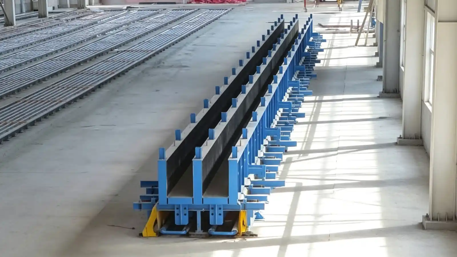
Custom Precast Column & Beam Moulds
Project-specific steel mould systems for precast columns and building beams, developed around the required sections, lengths, corbels, connections and factory process.
- Precast column mould systems
- Building beam mould systems
- Fixed, adjustable or hydraulic
Two clear project directionsStart with a precast column or a building beam.
Made around your componentSections, lengths and connection details define the mould.
Flexible operating optionsFixed, adjustable, movable or hydraulic arrangements can be reviewed.
Start with the structural member you need to produce
You do not need to select a mould mechanism first. Show us the column or building beam, and we can review the suitable mould direction around its geometry and your production process.
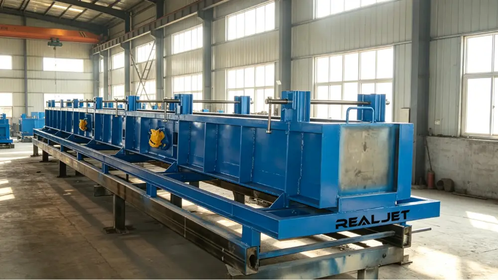
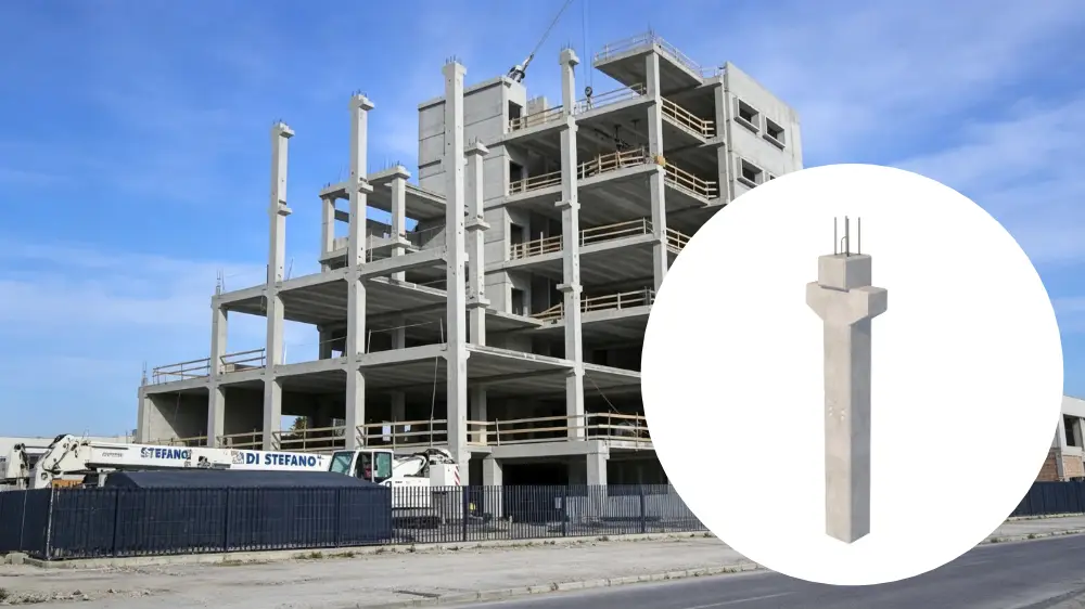
- Square or rectangular column sections
- Corbels, ledges and local formers
- Adjustable lengths and end details
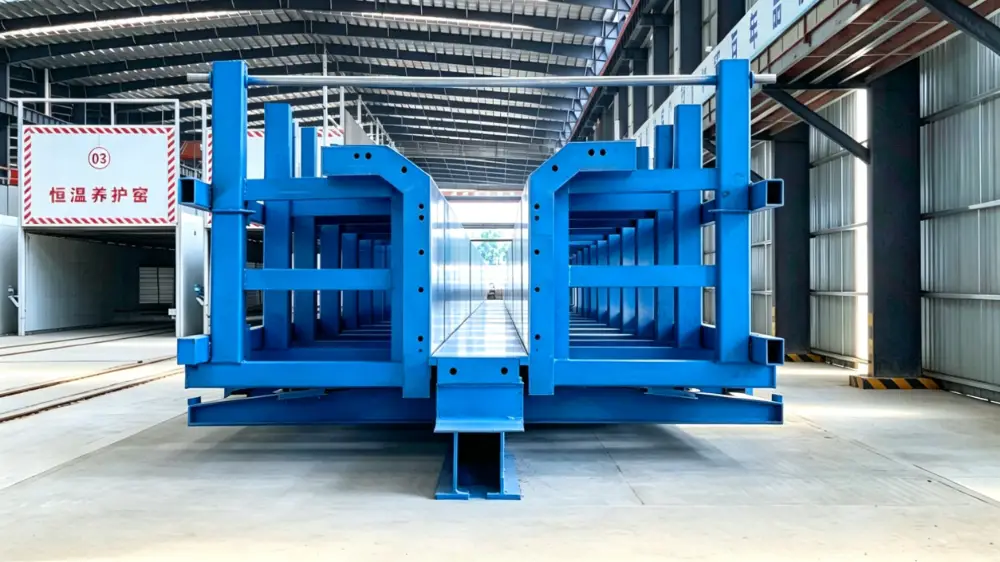
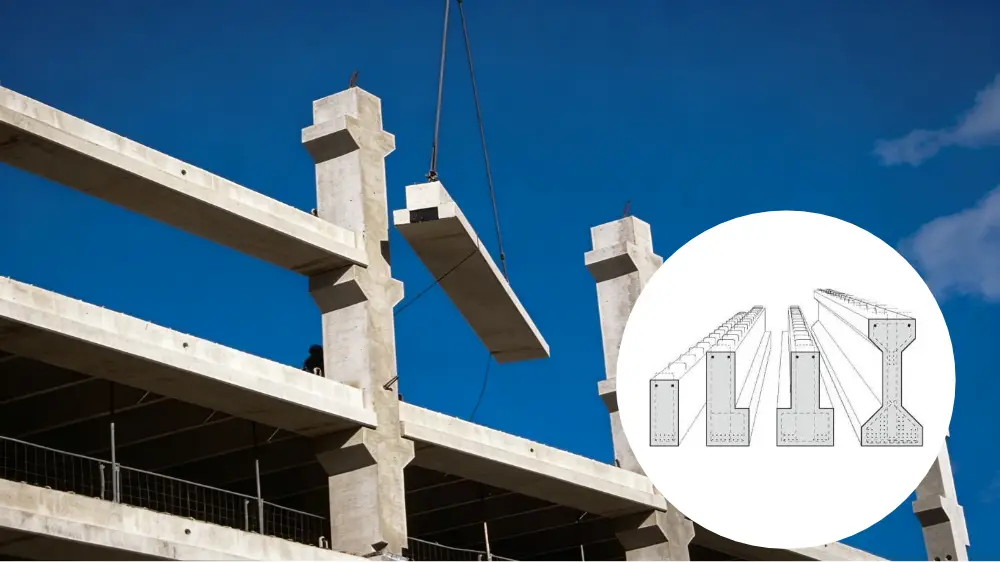
- Project-defined beam sections
- End details, lifting points and embedded items
- Related lengths within an approved product family
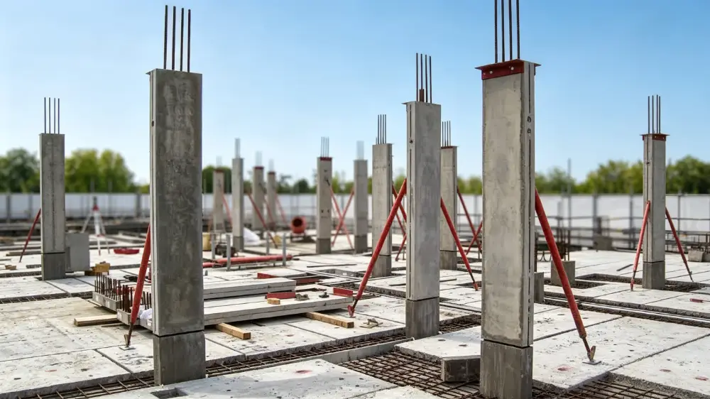
Recognise the finished component first
The finished member is the clearest starting point for discussion. Its profile, connection features and production sequence determine how the mould should be divided, supported and operated.
The operating method follows the component and factory process
These are engineering directions rather than fixed catalogue models. The final arrangement is confirmed after reviewing the member, required output, handling method and factory conditions.
Fixed mould
A direct arrangement for stable component families where the approved casting and demoulding sequence permits removable sides and ends.
Adjustable lengths
Adjustable stops or end forms may cover related lengths within an agreed component family and adjustment range.
Replaceable inserts
Project-specific formers may be developed for approved corbels, ledges, connection features or embedded details.
Hydraulic or movable
Hydraulic opening, closing or adjustment functions can be included where required by the agreed mould design and operating sequence.
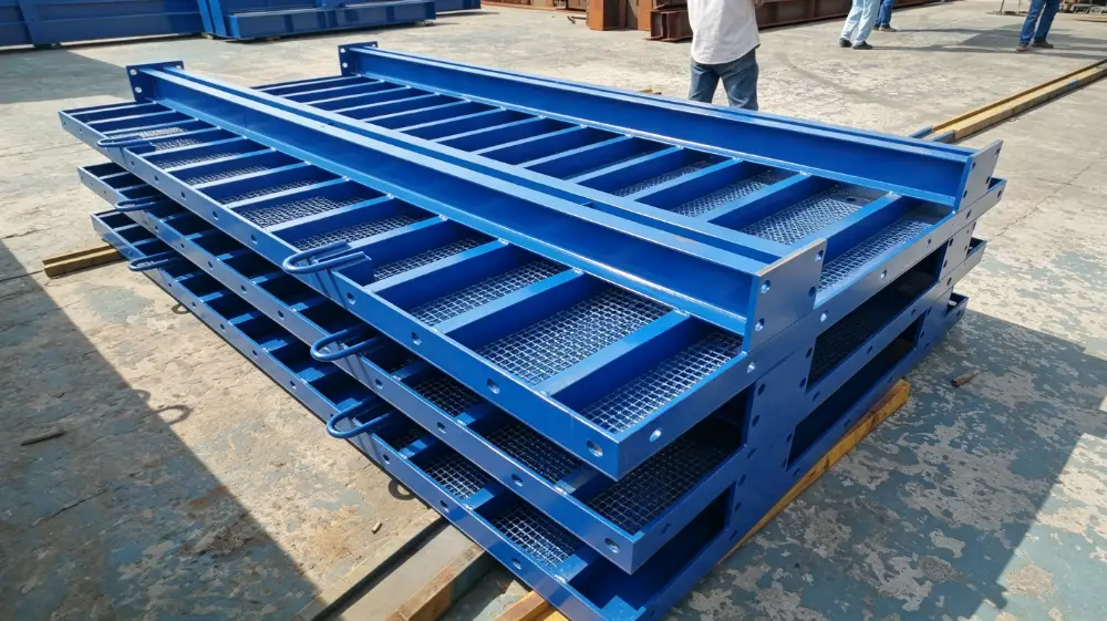
Configured around the component family
Start by showing us the column or beam you need to produce. A photo, approximate dimensions or an existing drawing is enough for an initial discussion.
You do not need to define the mould mechanism before contacting us.
- Cross-section and length range
- Corbels, ledges and haunches
- End details and connection plates
- Openings and embedded items
- Casting and demoulding direction
- Surface and dimensional requirements
A practical three-step technical discussion
The first message can be simple. Detailed engineering is developed progressively as the project information becomes available.
- STEP 01
Show the component
Send the column or beam type, a photo, approximate dimensions or an available drawing.
- STEP 02
Review the mould direction
We discuss the product family, casting process, changeover needs, demoulding and factory constraints.
- STEP 03
Confirm the project scope
Approved drawings, functions, interfaces and delivery boundaries are confirmed before manufacturing.
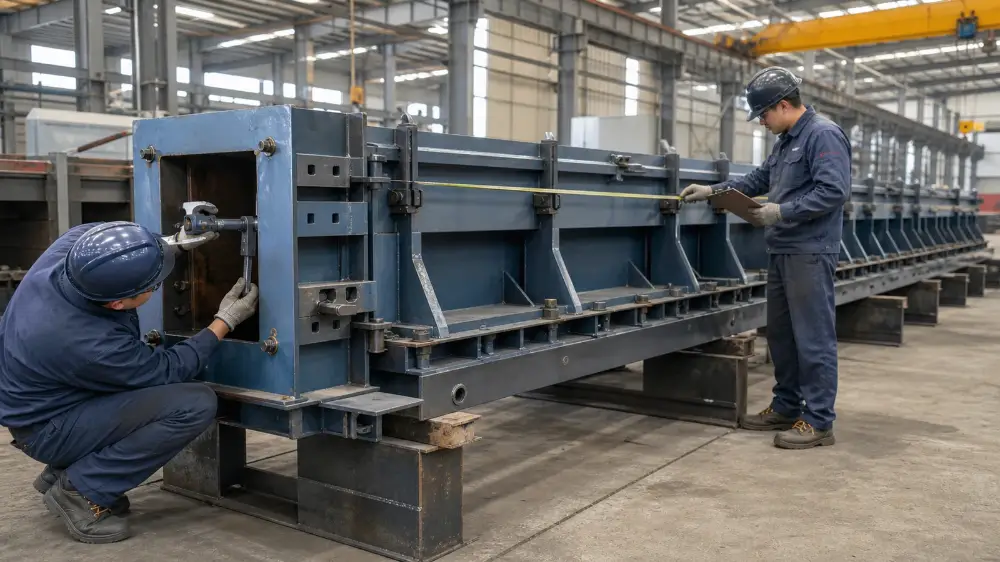
From component requirements to a manufacturable mould system
Realjet can connect process review, mechanical design, steel fabrication, hydraulic or mechanical integration, workshop assembly and project support around the agreed production objective.
Final dimensions, tolerances, functions, interfaces and delivery scope remain subject to approved project documents and technical review.
One team connects the component family, mould functions and manufacturing route
A custom column or building beam mould must coordinate member geometry, adjustable details, operating sequence and acceptance requirements.
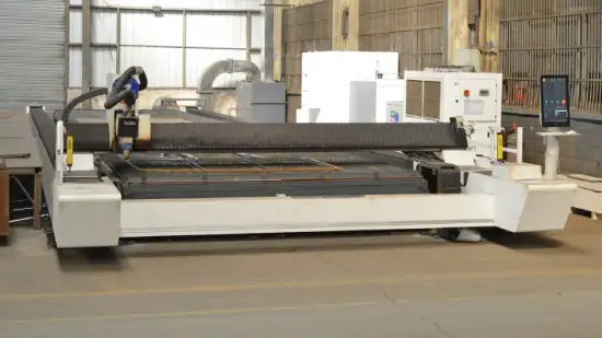
Component-family review
Sections, lengths, corbels, connections and available drawings are reviewed before the mould scope is defined.
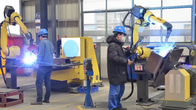
Connected fabrication
Cutting, forming, welding, machining and surface treatment are coordinated around the approved mould design.
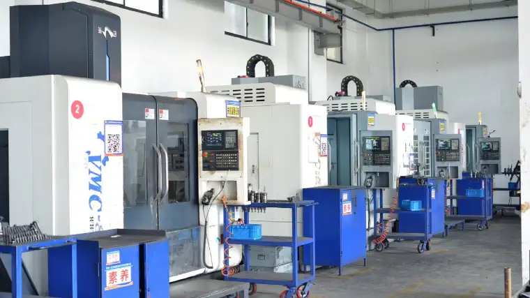
Integrated adjustment
End forms, replaceable inserts and mechanical or hydraulic functions are brought together for workshop assembly.
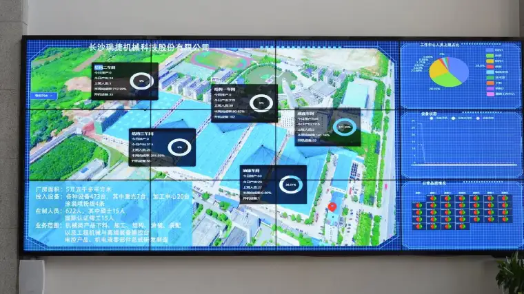
Inspection against the scope
Critical dimensions, interfaces, finish and final condition are checked against the agreed project documents before release.
Questions before you send an enquiry
If your project is still at an early stage, start with the information you already have.
Can one mould produce different lengths?
It may be possible to use adjustable stops or end forms for related lengths within an approved component family. The practical range depends on the member geometry, reinforcement, connection details and operating method.
Can the mould form corbels or connection details?
Project-specific inserts or local formers can be considered for approved corbels, ledges, plates and connection features. Their position and demoulding direction must be reviewed from the component drawings.
Do I need complete drawings before contacting Realjet?
No. A component photo, approximate section and length, or an early drawing can start the discussion. Approved technical documents are required before final design and manufacturing.
Should columns and beams use separate moulds?
In most projects they are treated as separate mould systems because their profiles, reinforcement, connections and handling differ. We review each component family before recommending the arrangement.
Can the mould use hydraulic opening or adjustment?
Yes, hydraulic functions can be reviewed where they support the agreed opening, closing or adjustment sequence. The final scope depends on moving mass, safety, controls and factory interfaces.
Tell Us What Column or Beam You Plan to Produce
Send a photo, approximate dimensions or a drawing. We will use it to discuss the mould direction; approved project documents are confirmed before final design and manufacturing.