
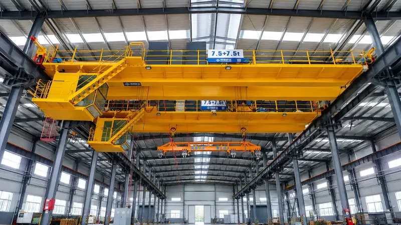
What a bridge girder order actually covers
An overhead travelling crane is built around one large weldment. The bridge girder carries the trolley and the rated load across the span, the end carriages carry the girder on the runway rails, and the two together pass every wheel load into the building structure. When a crane builder or a plant engineering team buys that steelwork, they are buying a weldment to drawing rather than a catalogue beam.
This guide covers that purchase: the inputs a fabricator needs before quoting a girder and end carriage package, the welding and machining standards that usually govern it, the tolerances worth writing into the order, and the evidence a buyer should expect before the steel is coated and loaded. Realjet manufactures welded and machined machinery components to customer drawings, and girder and carriage weldments are reviewed inside that scope through the contract manufacturing service rather than sold as a standard product.
Design, rating and conformity of the crane stay with the crane designer and the buyer's engineer. The fabricator builds the approved geometry, holds the stated tolerances and reports anything that cannot be met.
What has to be frozen before a quotation is useful
A girder quotation that arrives without a drawing basis cannot be compared with the next one. These items decide most of the cost:
- the crane class the girder is designed for, because the structure is sized for a duty and a load spectrum rather than for a single lift;
- span, rated capacity, trolley weight and the girder's own self weight;
- girder form, whether a welded plate girder with stiffeners or a box section, together with the plate grades and thicknesses for webs, flanges and diaphragms and the material standard they follow;
- the deflection limit the designer works to, and whether a camber is required;
- end carriage geometry: wheelbase, wheel diameter, gauge to the runway rails, and the structure that carries the wheels;
- the machining scope on the end carriages and any other machined interface;
- weld class, inspection level and the acceptance standard;
- finish system, with the surface preparation grade and the dry film thickness.
Two of these are usually missing: the duty class, because it lives in a calculation report rather than on a fabrication drawing, and the split between what the fabricator machines and what the buyer's team fits or shims on site. Writing both down prevents the argument that arrives when the girder reaches the assembly bay.
Deflection is worth stating explicitly, because it is a design constraint rather than a comfort target. CMAA Specification No. 70, maintained by the Crane Manufacturers Association of America and published through MHI, sorts top running bridge and gantry cranes into service classes and limits the vertical deflection produced by hoist, trolley and rated load to 1/888 of the span.
Welding standard: name it, and name the edition
Crane bridge weldments sit under more than one standard family, and the drawing has to say which one applies.
The American Welding Society's D14 committee covers welding of machinery and equipment. Its current machinery and equipment specification, AWS D14.0/D14.0M:2024, sets design, manufacture, quality, inspection and repair requirements for welded connections in machinery. The crane-specific document that came before it, AWS D14.1, applied to industrial and mill crane fabrications and to other overhead material handling equipment; it is now listed as historical, so a project that still names it should confirm what is being applied in its place. Where the girder is treated as structural steelwork, AWS D1.1 is the usual alternative, and some buyers specify both.
Whichever route is chosen, the drawing is expected to show the joint detail, the weld type and the weld size, as the scope of the D14 crane specification requires. A fabricator cannot price a full penetration butt weld in a bottom flange if the drawing shows an unspecified weld symbol.
Quality management is separate from acceptance. ISO 3834-2 sets welding quality requirements for comprehensive quality, and governs how procedures, personnel and inspection are controlled across the shop. Realjet works to ISO 3834-2 in its welding and fabrication operations, supported by documented quality control and dimensional release. A buyer sourcing girder weldments should ask about both layers, since a qualified welder is not the same thing as a managed welding system. The welding procedure and NDT scope belongs in the enquiry so the quotation states which welds are examined, by which method and against which acceptance level.
Camber, straightness and the tolerances that decide assembly
Two geometric requirements cause most of the trouble when they are missing from a drawing: camber and straightness.
A loaded girder deflects, and the crane designer may offset this by requiring the girder to be fabricated with a camber so the trolley does not run uphill toward midspan. Camber is a design decision, stated as a value at a defined location so that it can be measured, and normally verified with a taut wire or a laser before the rail is fixed and before coating.
The other is straightness and flatness. Welding heat pulls a long girder, and how far it moves depends on the section, the weld sequence and the restraint applied during fabrication. Welding distortion control is a method question for the shop, while the acceptance side is a tolerance question and belongs on the drawing as classes rather than as a general instruction to keep the girder straight.
ISO 13920 is the common reference for general tolerances on welded constructions. It provides classes for linear and angular dimensions and a separate set of classes for straightness, flatness and parallelism, so a buyer can ask for a tight class on the surfaces that carry the rail or the wheels and a looser class on web panels where nothing mates. Where an end carriage bolts to the girder, the hole positions and mating faces need their own tolerance basis, either through general tolerances or through a geometric scheme such as ASME Y14.5 or ISO 1101.
The splice belongs to the buyer's engineer. If a girder ships in sections, that joint is a structural connection designed by the crane engineer, and the fabricator's obligation is to build it to that design and hold the alignment at the joint, because a step in the top flange becomes an impact every time a wheel crosses it.
Where welding and machining meet: the end carriages
The end carriages show most clearly whether a supplier can machine as well as weld. If the wheels of a bridge do not run true to the runway rails, the crane crabs sideways, wheel flanges and rail heads wear early, and the drive loads rise. Field measurement uses diagonals taken between wheel contact points, and a well aligned carriage shows nearly equal diagonals. That alignment begins in the shop, with the bores, the wheel seat faces and the carriage structure built from a common datum rather than assembled from parts that each passed inspection on their own.
A workable sequence is to weld the carriage structure first, control or relieve the residual stress, then machine the wheel seats, bearing bores and mounting faces in one setting where machine capacity allows. Machining before welding loses the geometry that the welding heat moves. The same logic applies to any machined interface on a welded structure. Realjet's machining and assembly scope covers drilling and boring, deburring and subassembly work, so welding and machining can be quoted as one package with a single dimensional release. The buyer should still state which dimensions are inspected and reported, and from which datum.
Surface protection, marking and transport limits
Coatings protect the girder and also change fits. Blast cleaning and painting after machining affect seat faces and wheel bores unless those areas are masked, and the finish schedule should state the surface preparation grade and dry film thickness for each area and identify the surfaces left bare.
Transport sets one more limit. A single piece girder may exceed the road limits on the route, which is why long spans are often split with a designed splice. That division is the buyer's engineer's decision, while the fabricator advises on handling, packing and the practical weight of each piece. The shipping scope should say who supplies lifting lugs, which parts travel loose, and how exposed edges and machined faces are protected. Packing and marking rules for fabricated and machined parts are covered in the packaging and export scope guide.
Inspection evidence before shipment
Girder weldments are normally released against documents rather than against a visual check. A reasonable evidence set for this package includes:
- a dimensional report covering overall length and depth, camber at the stated location, straightness, and the end carriage wheelbase;
- a weld map cross referenced to the drawing, with examination methods and results;
- material certificates for plates and sections to EN 10204 3.1, traceable to the heat numbers used;
- a marking schedule so the site team can match each piece to the assembly drawing;
- a trial assembly record where the end carriages and the girder are assembled in the shop rather than on site.
Where a project repeats the same girder or carriage design, the first article inspection approach keeps the evidence proportionate: the first weldment is measured in full and approved, and the following ones are checked against the approved item.
How to compare the quotations
Price per tonne hides the differences that decide whether a bridge runs true. Ask each bidder to state, inside the quotation:
- the standard and edition used for welding, with the weld quality or acceptance level;
- the tolerance classes applied to the rail seat, the splice and the machined interfaces;
- the machining sequence and the datum scheme for the end carriages;
- the inspection and documentation package included, with NDT coverage;
- the finish system, and the assumed splice positions, plate grades and camber;
- any deviation from the drawing, listed as a deviation rather than absorbed quietly.
A quotation that answers those points can be compared with another one. One that does not is a price for an unknown scope, and the gap reappears later as rework, on site machining or a girder that will not sit square on the runway.
Realjet reviews girder and carriage enquiries from the approved drawings, the welding and tolerance basis the project applies, and the inspection evidence required at handover. Send the drawing package, the design data that fixes camber and duty, and the finish and transport requirements through the contract manufacturing enquiry route so the reply addresses the real scope.