
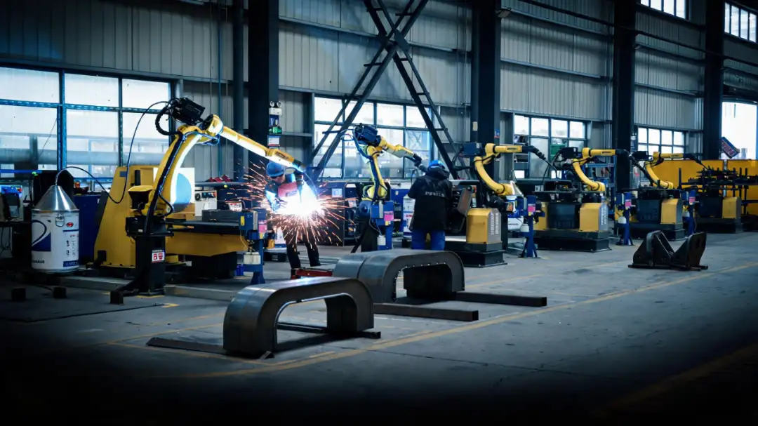
Why welded steelwork distorts
Welding heats a local zone to melting point while the rest of the part stays cool. The hot metal expands, is restrained by the colder surrounding material, and is plastically compressed. As the seam cools it shrinks and pulls on the structure. The result is residual stress and, once that stress overcomes the stiffness of the part, visible distortion.
Four common forms appear in fabricated steelwork. Transverse shrinkage narrows the seam. Longitudinal shrinkage bows a long member away from its neutral axis. Fillet welds produce angular distortion at the joint. Thin plate buckles when the compressive stress exceeds its capacity. None of these can be removed entirely. The practical target in contract manufacturing is to make the distortion small, predictable, and correctable by machining the functional faces after welding.
What to put in the fabrication RFQ
A buyer who needs a welded frame or machinery structure to a drawing should treat distortion control as a stated requirement, not a hope. The RFQ should name the welding code, the welding procedure basis, the permitted distortion on critical faces, and whether functional faces get a machining allowance for post-weld correction.
Structural welding is normally called up to a code such as AWS D1.1 or to a quality system such as ISO 3834 for fusion welding of metallic materials. These set acceptance limits for weld flaws and the qualification route for procedures and welders. They do not by themselves control distortion, so the buyer adds geometry requirements on top of the code.
State the allowance on machined faces clearly. A common shop practice, described in supplier welding guides such as the Fries distortion note, is to leave 3 to 5 mm of stock on functional faces so they can be milled true after welding. Without that allowance the supplier has little room to bring a distorted face back into tolerance.
Design choices that reduce distortion
Much of the distortion is fixed at the design stage. Throat thickness sized to the structural calculation rather than to habit keeps weld volume down. Seams placed symmetrically about the neutral axis pull in two directions instead of one. Intermittent welds replace continuous seams where tightness is not required, and X-groove preparations on thick plate weld both sides and roughly cancel angular distortion.
On the shop floor the strongest levers are sequence and restraint. Tacking from the centre outward, welding in a planned order that loads the part from both sides, and using back-step welding on long seams all reduce cumulative pull. Stiff fixtures hold critical dimensions while letting the seam shrink along a controlled path. Pre-setting a part against the expected distortion lets it pull into place as it cools. These are process decisions the supplier proposes, but the buyer sets the limit they must meet.
Stress relief and post-weld machining
When a welded structure will be precision machined afterwards, or must stay dimensionally stable in service, stress-relief annealing at roughly 550 to 620 degrees C removes much of the locked-in stress. Without it, residual stress can release during milling and distort the part a second time. Vibration stress relief is an alternative that avoids furnace time and oxidation, though the buyer should agree the method and its acceptance.
Post-weld machining is the only step that reliably brings a welded frame to tight tolerances. The proven sequence is weld, anneal where required, then mill the functional faces, fits and hole patterns. With enough allowance, flatness and position can reach the tenths of a millimetre range on welded frames. The machined interface tolerances are then checked against the drawing datums.
Where responsibility sits
The division of responsibility should be written before the order. The buyer or design authority defines the geometry, tolerances, welding code and machining allowance. The supplier proposes the welding sequence, fixtures, pre-set values and stress-relief route that meet those requirements, and records the parameters. The two sides should agree the distortion-critical items together, because an hour of coordination at the drawing stage avoids long arguments about straightening later.
Realjet manufactures welded machinery structures and steelwork to customer drawings and specifications. The welding procedure, distortion-control measures and machining allowance applied are the ones the buyer's specification requires.
Inspection and evidence to ask for
Ask for the weld inspection records that match the cited code, such as visual testing to ISO 17637 and imperfection limits to ISO 5817. For precision parts, request a dimensional report taken after stress relief and machining, referenced to the datums on the drawing. A trial assembly and dimensional check before shipment catches fit problems while correction is still cheap.
The welding procedure specification and NDT scope are covered in our notes for contract manufacturing. Read those alongside this article when you prepare the RFQ.
Preparing the RFQ
Distortion control is a buying decision, not a shop-floor detail. Define the welding code, the allowed distortion on functional faces, the machining allowance and the stress-relief route in the RFQ, and ask the supplier to state its sequence and fixture plan.
Realjet's contract manufacturing services cover welded fabrications machined to drawing, with inspection evidence matched to the specification you set.