
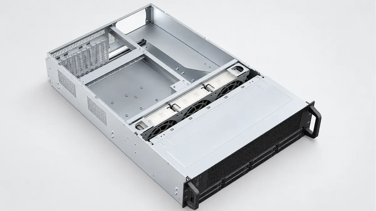
GPU Server Sheet Metal Chassis to your design
Source the bottom shell, structural panels or a joined metal chassis structure for your AI training or inference server. REALJET reviews your part drawings with the GPU tray, fan, power supply and rack interfaces before the manufacturing scope is agreed.
Choose the part and delivery condition
| Your order | Information that sets the scope |
|---|---|
| Chassis bottom shell | Flat pattern or formed drawing, datums and mounting features |
| Structural panel set | Individual part drawings, quantities and connections |
| Joined metal chassis | Assembly drawing, hardware list and delivery condition |
The order defines which panels arrive joined, which arrive loose and which hardware is included. GPU boards, fans, power supplies and server validation are separate from the metal chassis order unless explicitly agreed.
Fit it to the equipment around it
Show the common shell datums, tray support heights, fan opening positions and rail attachments on the assembly drawing. Identify removal directions so a dimensionally correct shell does not obstruct the hardware during service.
| Intended installation | Equipment interface to supply |
|---|---|
| AI equipment | AI training and inference GPU server |
Plan the manufacturing around these features
The steps below are proposed for the drawing review. Your material, geometry and acceptance requirements determine the final route, tooling and inspection provision.
Lay out the shell
Review bend access and hole positions against the flat pattern before blank preparation. Resolve openings or fasteners close to a bend before forming.
Form and locate the panels
Plan the bend order around tool access. Use the shell datum to locate structural panels; compare the open shell geometry before and after joining.
Finish the assembly interfaces
Review whether tray supports need machining after joining. Protect rack attachments and module entry edges during the specified finish.
Manufacturing capability for your component
| Your component feature | Existing process and its use | Confirm for your order |
|---|---|---|
| Shell blanks and returns | Laser, plasma and flame plate preparation; CNC press brakes. Cut and form the shell/panels before locating their connections. Choose the blank route and bend tooling for the actual material and openings. | Small return access, hole-to-bend distance and finished shell geometry. |
| Panel connections | Welded fabrication and post-weld finishing. Joined structural panels can use the fabrication sequence described for the chassis; the drawing determines whether welding or mechanical connections are appropriate. | Connection method and any captive-hardware installation. |
| Surface condition | Phosphating, powder coating and painting routes. Select a finish with the required appearance and protected contacts; review coating allowance at the tray and rack interfaces. | Material/finish compatibility and contact-area masking. |
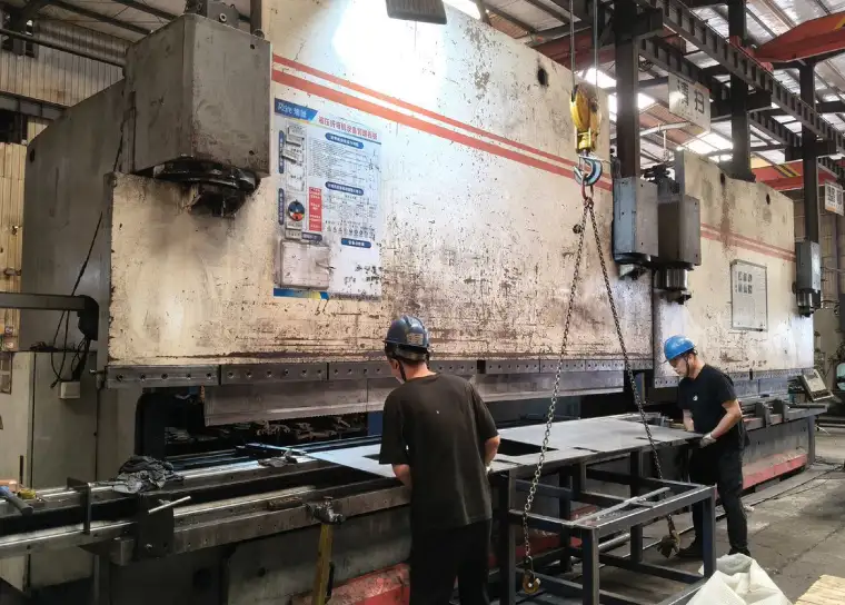
The existing CNC bending route supports a review of shell returns and panel features. Available press capacity is not a tolerance or bend-access guarantee for a server chassis.
Define what the first article must demonstrate
| Feature | Proposed check | Record to agree |
|---|---|---|
| Shell envelope and twist | Support the shell at the drawing datums; measure opposing corners, heights and panel offsets. A diagonal check alone does not establish hole position. | Envelope readings, support arrangement and drawing revision. |
| Tray, fan and rack interfaces | Measure fixing positions from the common datums, then trial-fit nominated mating parts or gauges in the finished shell. | Recorded hole/support dimensions plus separate fit observations. |
| Access and finished edges | Check cover fastening, tray removal and fan insertion paths using the agreed components. Inspect exposed edges and masked contacts. | Assembly checklist and any agreed finish observations. |
Identify the drawing revision, measurement datums and pass/fail limits before the sample is made. The quote confirms the available measuring setup, any mating fixture and whether a specialist test needs an external provider.
Packing for your next assembly step
Protect module entry edges and mounting surfaces. Specify loose panel sets or joined chassis so the packing supports and shipping volume can be reviewed. State the quantity and delivery city so packing volume and the requested delivery terms can be included.
Questions before you send drawings
How do you keep the panels aligned after joining?
The drawing review establishes a common shell datum, the panel locating arrangement and a joining sequence. The first article should be measured after joining and again where finishing may affect the mating interfaces. Tooling and measurement equipment are confirmed in the quote.
Can I order the shell without the complete chassis?
Yes. Identify the shell drawing and mating interfaces. Panels, reinforcement and purchased hardware are included only when they are listed in the quotation.
What should I send for the drawing review?
Send the dimensioned PDF, available STEP/DXF/DWG files and assembly view. Include material, finish, quantity, delivery city and drawing revision. Mark the features in the inspection plan that control acceptance.
Can we approve a sample before ordering repeat quantities?
Request a sample or pilot batch with the agreed dimensional report and any mating checks. Scope, timing and test provision are quoted after review; repeat supply follows the accepted drawing revision and any agreed sample changes.
Discuss your GPU server sheet-metal chassis
Send the part and assembly drawings with your quantity and required delivery condition. Highlight the interfaces and checks listed above that matter to your order.
Attach files in your email application. To arrange file transfer first, use the enquiry form.