
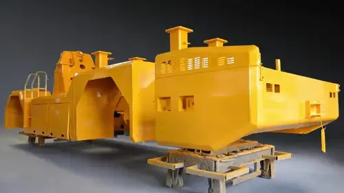
Why a welded frame moves after the first cut
A heavy frame is welded, allowed to cool, and delivered to the machining centre. The first face mills clean. Bores are opened to size and the part is measured while still clamped, so it passes. The clamps come off and the frame relaxes by two or three tenths of a millimetre. A bearing bore that was round an hour ago is now out of round, and the alignment between two bores at opposite ends of a three-metre frame no longer holds.
The cause is residual stress. Weld metal shrinks as it solidifies and cools, and the surrounding cold plate restrains that contraction. The result is a locked pattern of tension and compression that stays in the component as long as nothing disturbs the balance. Machining does disturb it. Every cut removes a layer of material that was carrying part of the load, and the remaining stress redistributes itself through the part. Cold forming and plate rolling add their own contribution before a single arc is struck.
On a made-to-drawing weldment with machined interfaces, stress relief decides whether the finished part holds that geometry in service, and whether it still holds it when the customer measures the part after delivery.
What stress relief actually does
Stress relief heats the whole component to a temperature high enough for the steel to creep slowly, but low enough that no phase change occurs. For carbon and low alloy structural steels this is normally in the range of about 550 to 650 °C, well below the lower critical temperature. The part is held at temperature, then cooled slowly in the furnace so that new thermal gradients do not rebuild the stress that was just removed.
At that temperature the yield strength falls far enough that the locked elastic strain converts into a small amount of plastic flow. Peak residual stress drops substantially, though not to zero, and the microstructure is essentially unchanged. Hardness moves very little. This is what separates stress relief from normalising or full annealing, which work above the critical temperature and are chosen to change structure and mechanical properties instead of only relieving locked strain. Heat treaters describe the distinction and the usual temperature window in their own process notes, for example HTR on stress relief annealing.
What it buys a buyer is dimensional stability during and after machining. It does not repair an unsound weld, sloppy interpass control, or a machining sequence that ignores how the part is supported.
When the requirement is already fixed
Some orders do not involve a decision, because the governing specification already answers it.
Pressure-retaining work is the clearest case. ASME Boiler and Pressure Vessel Code, Section VIII Division 1, UCS-56 requires post-weld heat treatment for P-No. 1 carbon steel above roughly 32 mm nominal thickness, at a holding temperature of about 595 to 650 °C, with holding time related to thickness at around one hour per 25 mm and a one-hour minimum. Thicker or alloyed material brings its own tables.
Structural steel is different. EN 1090-2 does not impose post-weld heat treatment as a routine requirement for ordinary building frames, so on a structural order the obligation comes from the project specification, the execution class, or the designer's own note rather than from the code alone. A fabricator who assumes EN 1090-2 covers the question will eventually be asked for a heat treatment chart that no one ordered.
Sour service pushes in the other direction. Where ISO 15156 or NACE MR0175 applies, hardness limits in the weld and heat affected zone usually make stress relief the normal route, and the purpose is hardness control as much as dimensional stability.
The fourth case is commercial rather than regulatory. Nobody has specified heat treatment, but the part has machined bores, flat mounting faces, or pivot points that must stay aligned after the customer bolts something to them. That is a design decision, and it belongs to whoever owns the drawing.
The furnace is the real constraint
Whole-component treatment requires a furnace that will accept the finished envelope, including any brackets, lugs and stub shafts that were welded on. Furnace length, width, height and maximum load are hard limits, and they are worth asking about at quotation stage rather than after the design is frozen.
When the part is too large, the alternative is local heat treatment with resistance heating pads, insulation and thermocouples, run to a written procedure. Local treatment relieves the heated band and a transition zone around it. It is a reasonable engineering answer for a field joint on a pipeline. It is a weaker answer for a long frame whose problem is the interaction between welds at opposite ends, because the unheated middle keeps its stress and continues to pull against the relieved ends.
Some fabricators treat in house, some send parts to a specialist heat treater, and some do both depending on size. Which route applies changes the schedule and the evidence trail, so it should be stated rather than assumed.
| Route | Fits | Main limitation | Ask for |
|---|---|---|---|
| Furnace, whole component | Frames that fit the furnace envelope | Furnace size and load limit; transport if subcontracted | Furnace dimensions, load capacity, uniformity survey, chart per part |
| Local resistance heating | Oversized or site-built structures | Relieves only the heated band | Written procedure, thermocouple layout, band width |
| No treatment | Thin, lightly restrained weldments with no post-weld machining | Residual stress stays in the part | Design justification from the drawing owner |
Sequence matters more than the cycle
The usual sequence on a weldment with machined interfaces is rough machine, stress relieve, finish machine. Rough machining removes the bulk of the allowance and shifts the stress balance; heat treatment then relaxes what remains; finish machining takes the part to final size with little material left to disturb it.
Two practical points follow. First, the drawing has to leave enough allowance for the movement that occurs between rough and finish machining, and that allowance is larger than most first-time buyers expect on a long frame. Second, parts are sometimes given a second, lower temperature treatment between rough and finish machining when the bores are tight and the frame is heavily welded. That doubles the cycle time and should be priced knowingly rather than discovered later.
Stress relief also changes the surface. Oxide and scale form in the furnace, and any area that was finish machined before treatment will need protection or rework. If the component is painted, the heat treatment comes before surface preparation, never after.
What to put in the RFQ
A stress relief requirement that arrives as one line on a drawing usually generates a round of questions. The version that does not is specific about the following:
- Base material grade and a thickness map, so the heat treater can confirm the temperature and hold time.
- Extent and size of welding, including repairs and any attachment welds that will be removed.
- The governing standard, named by number, if a code applies.
- Holding temperature range and hold time, or a reference to the code table that sets them.
- Heating and cooling rate limits, and the maximum temperature at which the part may leave the furnace.
- Whether treatment is by furnace or local, and who decides if the part does not fit.
- Support arrangement inside the furnace, because a long frame that is poorly supported can distort more in treatment than it would have moved in machining.
- Record requirements: chart, procedure, equipment calibration, and whether hardness testing is wanted.
One further item belongs in the RFQ even though it is not a process parameter: who owns the risk if the part distorts during treatment. A fabricator can stress relieve to a correct cycle and still hand back a frame that needs straightening.
Records and evidence
ISO 17663:2023 sets out quality requirements for heat treatment carried out in connection with welding, and it is the framework most auditors will expect to see behind a heat treatment certificate. It covers the procedure specification, personnel competence, equipment validation including furnace temperature uniformity surveys, thermocouple number and placement, and the records themselves. Records are normally kept for at least five years. The standard sets the control system, not the temperatures, which still come from the product code or the drawing.
Reading it alongside ISO 3834-2, the welding quality requirement that governs the fabrication itself, gives a buyer a useful test of a supplier. A fabricator who can produce a heat treatment chart with the part number on it, traceable to a validated furnace and a written procedure, is usually also controlling preheat and interpass temperature. One who offers a certificate with no chart attached is asking to be taken on trust.
Who decides what
| Decision | Owner | Why it sits there |
|---|---|---|
| Whether treatment is technically required | Drawing owner or designer | Depends on service, tolerances and code applicability |
| Temperature, hold time and rates | Fabricator, to the named standard | Requires material and thickness data |
| Furnace versus local route | Fabricator, disclosed to buyer | Depends on available equipment and part size |
| Machining allowance for movement | Drawing owner, with fabricator input | Tied to the tolerance on the finished part |
| Records and traceability | Fabricator | Part of the delivered evidence package |
| Distortion risk and straightening | Negotiated, stated in the order | Neither party controls it alone |
Where a drawing says nothing, the safe reading is that nothing is required, and that is rarely what the drawing owner intended.
Placing the requirement
On a made-to-drawing weldment, stress relief sits between fabrication and finish machining, and it is one of the few process steps that can be added late at high cost or omitted early at higher cost. Deciding it while the drawing is still open, and writing it into the enquiry with the temperature, the route and the records, removes most of the argument that otherwise arrives with the first out-of-tolerance bore.
Realjet builds welded machinery structures to customer drawings, including frames, chassis, bases and assemblies that go on to machined interfaces. The contract manufacturing capability page sets out the fabrication, machining and inspection scope, and the enquiry route for parts where heat treatment has to be sequenced with machining.