
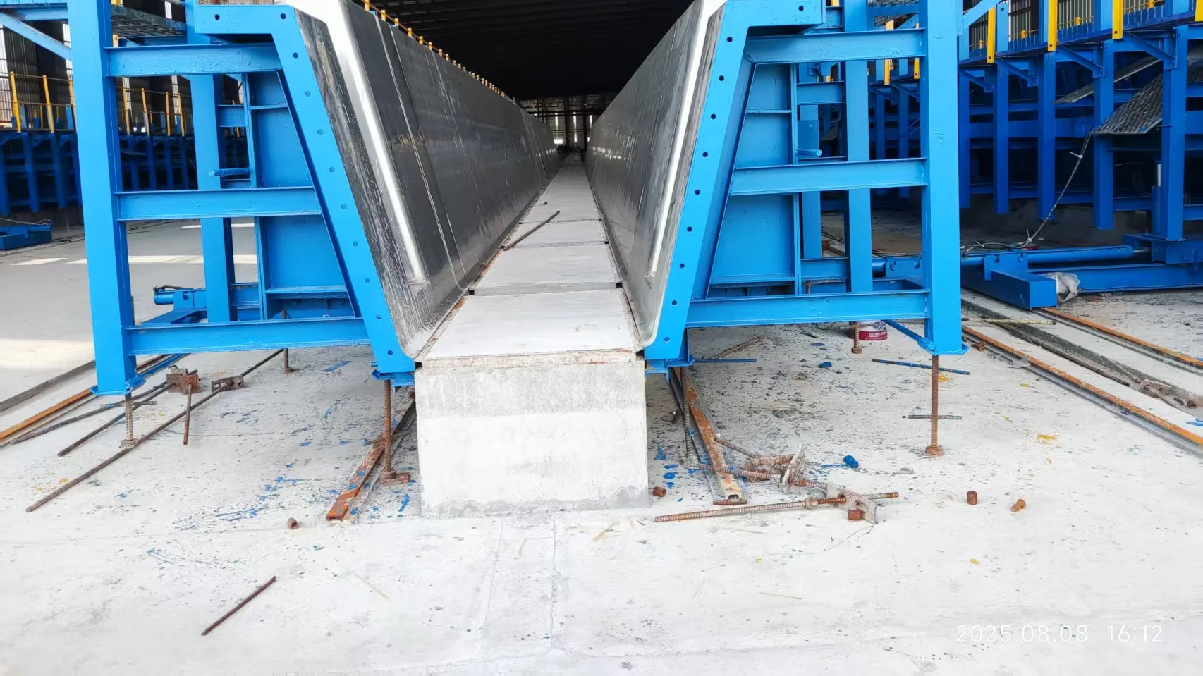
The tolerance chain starts in the mould
A precast component is only as accurate as the cavity it was cast in, and the cavity is a welded steel structure built to its own tolerances. Those two sets of numbers are related but not the same, and the gap between them is where most dimensional disputes begin.
The mould does not get the whole component tolerance to itself. Part of that allowance covers movement during casting and vibration, thermal effects, stripping and handling, stacking in the yard, and the journey to the final position. If the mould takes the entire allowance, the component arrives on site with nothing left.
A buyer who sets the mould tolerance deliberately, as a fraction of the component tolerance, gets a mould that can produce acceptable units. A buyer who repeats the component tolerance on the mould drawing gets an expensive mould that produces marginal units.
Which document governs the numbers
Component tolerances for precast concrete come from a small number of documents, and they are in transition, which is worth knowing before writing an order.
The Precast/Prestressed Concrete Institute issued PCI 135, Specification for Tolerances of Precast Concrete, in 2025, superseding the tolerances in the older MNL 135. It is written in mandatory language and covers production, erection and interfacing tolerances, including fabricated embeds and erection hardware. PCI states that MNL 116 and MNL 117 will be amended to reference it before July 2026, and that ACI 117 is planned to reference PCI 135 in place of ITG 7. The PCI tolerances page sets out the transition.
For European projects, EN 13670 governs execution of concrete structures and carries its own tolerance classes. A project that names both without saying which governs a given dimension invites two readings of one drawing.
The practical rule: name one governing document, name the tolerance class or table, and state in the mould specification how much of that allowance the mould is expected to use.
Three families of tolerance, and only one belongs to the mould
PCI separates tolerances into component, erection and interfacing categories, and the distinction is useful at order stage because it tells the buyer which checks belong to the mould supplier and which belong to somebody else.
Component tolerances describe the finished unit: length, width, depth, squareness, flatness of a face, position of cast-in items. Erection tolerances describe where the unit ends up on site, and no mould can control them. Interfacing tolerances describe the relationship between adjacent units, joint widths and bearing areas, and these are the ones that catch moulds built to nominal dimensions in isolation.
An element can be inside its own component tolerance and still fail to fit the element next to it. That is why the mould drawing has to be checked against the interface, not only against the nominal section.
The dimensions that get checked
A dimensional schedule for a project specific steel mould usually covers the following, and each item needs a value, a method and a record:
- Cavity length, width and depth at defined stations
- Squareness of the cavity, checked as diagonals rather than angles
- Flatness of the casting face, expressed over a stated gauge length
- Step and gap at panel joints and at the junction between fixed and moving parts
- Position of blockouts, chamfers, cast-in plates and sleeve holes
- Position of prestressing anchorages and duct exit points where relevant
- Camber or longitudinal profile where the component is built to one
- Position of lifting point recesses
Two deserve attention. Joint step is what a client sees on a finished face and what lets grout escape, and it changes as a mould wears. Cast-in item position decides whether the element can be connected on site, and it is the item most often left to the mould builder's reading of a general arrangement drawing.
Diagonals catch what a length alone hides
A long mould can measure correctly along its length and still be out of shape. If the two side forms are set parallel but the assembly is skewed, the length check passes and every element cast in it is a parallelogram.
Measuring both diagonals, and recording the difference rather than the two values, exposes skew immediately. It is a cheap check with a steel tape, and it matters more as moulds get longer, because the same angular error produces a larger linear deviation at the ends.
The same logic applies to a mould assembled from modules. Each module can be within tolerance while the accumulated set-out drifts, so the diagonal should be checked on the assembled mould, not only on the panels in the workshop.
A steel structure tolerance is not a cavity tolerance
Moulds are welded steel structures, and EN ISO 13920 covers dimensional tolerances for welded constructions. A fabricator who builds to it has built an acceptable steel structure, which is not the same as an acceptable mould. A side form frame can satisfy that standard and still put the casting face half a centimetre out of position, because the standard governs the steelwork, not the geometry of the concrete it produces. The mould specification has to state cavity tolerances separately and say that they govern where the two differ.
The distinction explains a common argument at handover. The supplier reports steelwork within EN ISO 13920, the buyer measures a cast component outside the PCI or EN 13670 allowance, and both are right. The missing document is the cavity tolerance schedule.
Camber and the shape you actually want
Prestressed elements are not straight in service. The design gives a camber, and the mould has to be built to the shape that produces it, which may not be the nominal section drawn on the general arrangement.
Two questions belong in the enquiry. Who issues the camber or profile values, and at what stage? And is the mould to be built to the no-load profile or to a compensated profile that anticipates elastic shortening and deflection?
For long-line beds the same issue appears as a vertical profile along the bed, which interacts with settlement and with the survey datum used at installation. A mould that is flat to a tight tolerance but set on a bed with a longitudinal fall still produces elements that are not.
Moving parts and repeatability
On a mould with opening side forms or an internal form, the tolerance that matters in production is not the one measured in the workshop with the mould closed by hand. It is the one that repeats after two hundred cycles.
Three items decide that. The closed position must be positively located by stops or wedges rather than by the cylinder, so closing force does not set the geometry. Hinges and guide pins wear, which shows as a progressive change in joint step, and seals compress, which changes the gap at the joint line.
The order can require adjustable stops, replaceable wear parts at the locating points, and a stated closed position tolerance measured after a full open and close cycle under power. That last requirement is the one that separates a workshop demonstration from a production tool.
Measurement conditions and the record
A number without its measurement conditions is not evidence. A dimensional report should state the temperature at measurement, the instrument and its calibration status, whether the mould was supported as it will be in service, and where the reference points were taken from.
Steel tape and laser distance meters read differently over ten metres, and a tape that has been dropped reads differently again. For long moulds a total station or laser tracker is the practical instrument, and the report should say which was used. The record itself should be a table of nominal, actual and deviation per item, signed and tied to the drawing revision. A photograph of a tape held against a side form is not a dimensional record.
Trial assembly and the first component
Trial assembly in the supplier's works is where the geometry is proven before transport, and it is the moment to witness the checks rather than repeat them on site. For a large mould it should include the full open and close cycle, the fit of internal forms in both positions, and the assembly of any end forms used across a range of lengths.
The final proof is the first component. Measuring the first unit cast at the defined stations closes the loop between steel and concrete geometry, and includes vibration, concrete pressure and stripping.
A sensible order requires both: a dimensional report from trial assembly, and a first component measurement with the results compared against the same schedule.
Writing the schedule into the order
| Item | Value to state | Evidence to require |
|---|---|---|
| Component tolerance basis | PCI 135, ACI 117, EN 13670 class, or project specification | Named document and table |
| Mould share of allowance | The fraction or value the mould may use | Stated on the mould drawing |
| Cavity dimensions | Nominal plus tolerance at defined stations | Dimensional report, station by station |
| Squareness | Diagonal difference limit | Both diagonals recorded |
| Casting face flatness | Value over a stated gauge length | Straightedge and wedge readings |
| Joint step and gap | Limit at each joint type | Feeler gauge record |
| Cast-in item position | Tolerance in plan and elevation | Survey or jig record |
| Camber or profile | Source of values and stage issued | Profile table on the drawing |
| Closed position repeatability | Tolerance after powered cycle | Cycle test record |
| Wear parts | Replaceable at locating points | Parts list |
Who owns what
| Decision | Owner | Why it sits there |
|---|---|---|
| Component tolerance and class | Designer or specifier | Comes from the structure and the interface |
| Mould share of the allowance | Buyer, agreed with supplier | Commercial and technical trade-off |
| Cavity tolerance schedule | Supplier, approved by buyer | Part of the mould design |
| Camber values | Designer | Structural behaviour, not mould making |
| Measurement method and instrument | Supplier, agreed by buyer | Has to suit the length and the record |
| Trial assembly and report | Supplier | Delivered evidence |
| First component measurement | Buyer, with supplier support | Confirms the whole chain |
| Interface check with adjacent units | Buyer or designer | Requires the neighbouring geometry |
Where to take the question
Tolerances become a specification once the component tolerance, the mould share and the measurement method are written down together. Realjet designs and manufactures project specific steel moulds, with the cavity geometry, opening method and dimensional record agreed against the component drawing.
The precast concrete moulds overview shows how the families are organised, the bridge and transportation moulds category covers the long structural moulds where accumulated error matters most, and the T-girder moulds page illustrates a mould type where camber, end forms and length variants all bear on the tolerance schedule. Sending the component drawing with the governing tolerance document and the interface details attached is enough to set the schedule on a common basis.