
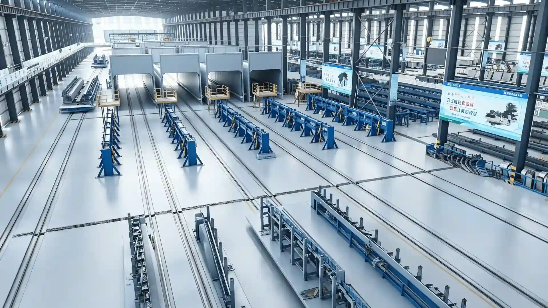
Why tensioning and spinning are one sequence
On a spun pile line, tensioning and centrifugal spinning are not two separate jobs. Tensioning places the reinforcement under the designed prestress while the cage sits in the mould, and spinning then compacts the concrete around that stressed cage. If the prestress or the mould alignment is wrong at the handoff, the spinning stage cannot correct it.
Treat the two stations as one process with a defined transfer, and decide the checks at the boundary before you buy the equipment. The two stations also share the same mould, so a change to one affects the other, and specifying them together avoids a line that cannot reach its design output.
Confirm the tensioning setup before moving the mould
The pile tensioning machine applies the prestressing load through the mould-end anchorage, using the force and elongation set by the approved pile design. The tensioning station must connect correctly to the mould and the reinforcement anchorage, and the applied load should be measurable and recorded.
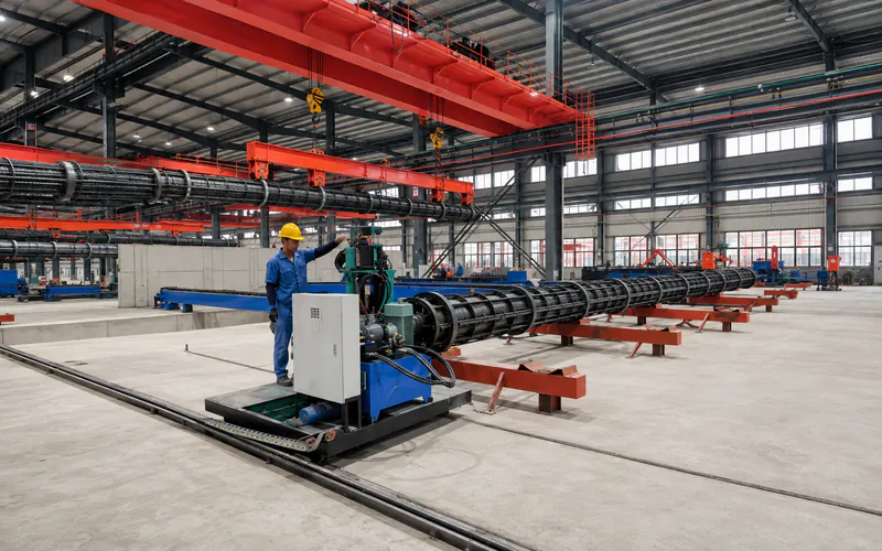
Prestressing Tensioning Machine for Spun Piles
The tensioning machine applies the approved prestress to the reinforcement inside the mould. Its force, stroke and anchorage interface must match the pile design before the mould moves to spinning.
View equipment detailsBefore the mould leaves the tensioning station, confirm the force, the elongation and the anchorage seating against the design. The load path runs from the anchorage through the mould ends, so any mismatch here carries straight into the spinning and curing stages.
Move the mould to the spinning station
Once tensioning is verified, the loaded mould moves to the centrifugal spinning machine. On most lines this transfer runs at ground level, driven by a friction-wheel unit that contacts the trolley and positions it at the spinning rollers.
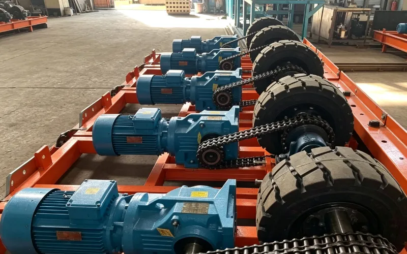
Friction-Wheel Drive for Production Trolleys
The friction-wheel drive moves the loaded mould from the tensioning station to the spinning machine. Its force, speed and stopping points must suit the trolley load and the transfer route.
View equipment detailsThe drive must suit the loaded mould mass and the travel route, with stopping points matched to the spinning station. Because the reinforcement is already under tension, the transfer should hold the mould steady and avoid shock loads that could disturb the cage or the anchorage.
Run the spinning stages on the loaded mould
The spinning machine rotates the filled mould through controlled stages to compact the concrete and form the hollow pile section. The roller arrangement and drive are matched to the mould family, and the operating recipe is set for the concrete mix and the pile section during process development.
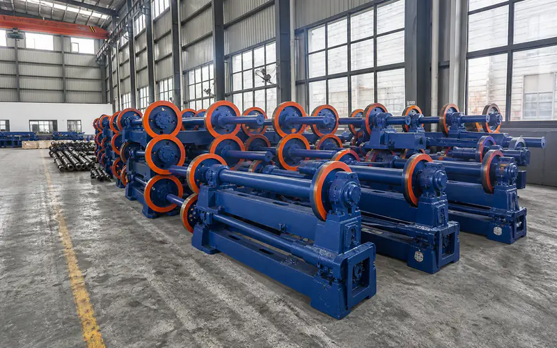
Centrifugal Spinning Machine for Concrete Piles
The spinning machine rotates the loaded mould to compact the concrete and form the hollow section. Its rollers, drive and recipe must suit the mould family and the pile section.
View equipment detailsSpinning is typically run in stages from low to high speed, with the early stages distributing the concrete and the later stages compacting it and removing excess water. The running-ring and roller alignment must hold through the speed range, and the mould-end connections must keep the prestress intact while the mould turns.
Match the concrete fill to the spinning result
The amount of concrete placed in the mould sets the final wall thickness after spinning removes the excess. Too little leaves a thin, weak section; too much overloads the mould and the spinning drive. The fill volume is worked out from the pile geometry and the mix, then checked during process development rather than copied from another product.
Because the cage is already stressed when the concrete goes in, the filling method should place the mix evenly without disturbing the reinforcement or the anchorage. The filling and the first low-speed spinning stage are therefore planned together, not as separate steps.
Keep prestress and alignment through the handoff
The risk at the tensioning-to-spinning boundary is losing what tensioning achieved. Check that the mould-end anchorage stays seated during transfer, that the running rings sit correctly on the spinning rollers, and that the tension is not released or changed before spinning starts.
The approved prestressing design fixes the force and the verification method, so the equipment and the procedure should both follow it. Process settings and acceptance checks for the spinning recipe are established for the agreed equipment and product during commissioning, not assumed from a generic speed chart.
Keep a tensioning record at the tensioning station and a transfer check at the spinning station, so any drift in force or alignment is caught at the boundary instead of after demoulding.
Confirm the coordination in the line layout and contract
Because tensioning and spinning share the mould and the reinforcement, their coordination belongs in the line layout and the supply scope, not in a separate note. Realjet can include both stations in a coordinated package and confirm the force, stroke, anchorage interface, roller spacing and drive against your pile drawings and the selected mould before the proposal is finalised.
The line layout should put the tensioning and spinning stations close enough that the transfer is short and protected, with clear access for the crane and the trolley. Document the agreed force, stroke, roller spacing, drive and recipe in the project file so commissioning and later service follow the same reference.
If you are planning a new line, review the spun pile production line solution and share your prestressing design and product sizes so the tensioning and spinning stations are matched from the start.