
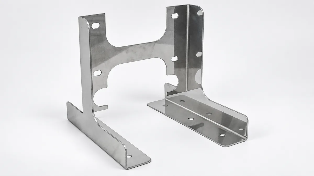
Heat Exchanger Mounting Brackets to your design
Source a metal bracket that fixes your heat exchanger to its cooling-equipment frame. REALJET makes the non-wetted support to your mounting pattern, stand-off dimensions and connection details.
Choose the part and delivery condition
| Your order | Information that sets the scope |
|---|---|
| Individual bracket | Bracket profile, offsets and fixing points |
| Welded support bracket | Joint drawing, support position and weld requirements |
| Left/right bracket set | Handed part numbers and installed spacing |
This is an external mechanical support, not a heat exchanger or pressure-containing part. AI CDU and battery-storage cooling versions each follow their equipment-specific design.
Fit it to the equipment around it
The bracket must place the heat exchanger correctly while leaving room for fasteners, piping and removal. Include the equipment weight and support arrangement in the design information. Identify which clearance is needed for routine service rather than installation alone.
| Intended installation | Equipment interface to supply |
|---|---|
| AI equipment | AI cooling heat exchanger |
| Battery storage equipment | Battery-storage thermal management heat exchanger |
Plan the manufacturing around these features
The steps below are proposed for the drawing review. Your material, geometry and acceptance requirements determine the final route, tooling and inspection provision.
Review offsets against the exchanger
Review bend radii, fixing holes and tool access against the mounting-interface drawing. Identify handed parts and their installed spacing.
Form or join the specified support
Use a forming route for a bent bracket or review restraint and joining order for a welded support. Do not assume the same route suits both designs.
Finish the mounting contacts
Review any required face/slot finishing after joining. Surface treatment must preserve the specified fit and corrosion requirements.
Manufacturing capability for your component
| Your component feature | Existing process and its use | Confirm for your order |
|---|---|---|
| Bracket offset | Plate preparation and CNC bending. Form the support offset from its frame-side datum, with bend access reviewed before blank preparation. | Bend/tool access and handed part geometry. |
| Joined support features | Welded fabrication and machining where required. Use the joining and interface-finishing route only for the features present in the drawing. | Free-state offset after joining and any machining access. |
| Surface protection | Deburring and coating/painting routes. Finish contact edges and review the specified protection for the equipment environment. | Contact masking and paired-support fixture/test provision. |
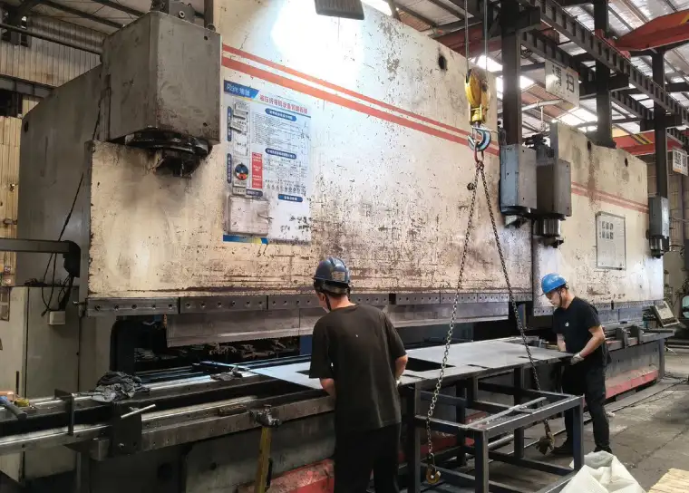
The established bending equipment and welded-fabrication route can be reviewed for this support. Bent and welded versions are assessed separately.
Define what the first article must demonstrate
| Feature | Proposed check | Record to agree |
|---|---|---|
| Fixing faces and offset | Reference the frame-side face and measure the exchanger-side offset, angle and hole positions. | Offset/angle and hole results tied to the drawing datums. |
| Left/right spacing | Check a paired set in the installed support arrangement when ordered; do not establish spacing from two unrelated part measurements. | Pair identification, spacing result and support setup. |
| Removal and load if ordered | Trial the nominated exchanger/dummy for access. Review loading separately with the actual support and acceptance limits. | Access observations and separately scoped load-test record. |
Identify the drawing revision, measurement datums and pass/fail limits before the sample is made. The quote confirms the available measuring setup, any mating fixture and whether a specialist test needs an external provider.
Packing for your next assembly step
Label left and right parts where needed and protect mounting faces. Pack slender offsets so they cannot be bent by the weight of other components. State the quantity and delivery city so packing volume and the requested delivery terms can be included.
Questions before you send drawings
How do you check a handed bracket pair?
Identify both parts and establish their common frame-side datums. The inspection plan can check offsets separately and the installed spacing as a pair, using the nominated exchanger interface or fixture.
Is the bracket in contact with coolant?
The proposed product is a non-wetted mounting bracket. Any coolant-contact or pressure-containing part needs a separate material, joining and test review.
What should I send for the drawing review?
Send the dimensioned PDF, available STEP/DXF/DWG files and assembly view. Include material, finish, quantity, delivery city and drawing revision. Mark the features in the inspection plan that control acceptance.
Can we approve a sample before ordering repeat quantities?
Request a sample or pilot batch with the agreed dimensional report and any mating checks. Scope, timing and test provision are quoted after review; repeat supply follows the accepted drawing revision and any agreed sample changes.
Discuss your heat exchanger mounting bracket
Send the part and assembly drawings with your quantity and required delivery condition. Highlight the interfaces and checks listed above that matter to your order.
Attach files in your email application. To arrange file transfer first, use the enquiry form.
AI server and data-center components → · Battery storage, EV charging and solar components →