
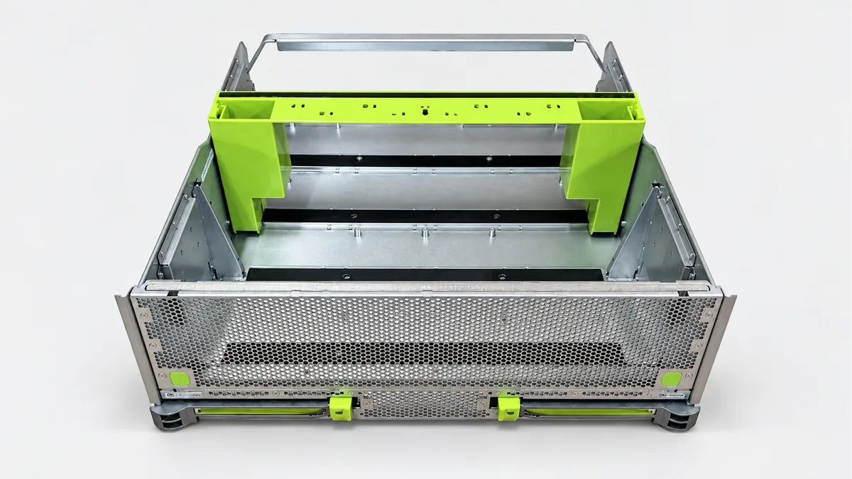
GPU Carrier Trays for AI Servers to your design
Order the metal tray that supports your GPU baseboard assembly and locates it inside the server chassis. REALJET manufactures the formed tray and drawing-defined reinforcement to your part and assembly drawings.
Choose the part and delivery condition
| Your order | Information that sets the scope |
|---|---|
| Formed tray | Tray profile, board-support positions and attachment details |
| Tray with reinforcement | Reinforcement drawing, joint details and required finished condition |
| Pilot tray for assembly review | Mating chassis, board envelope or approved checking fixture |
Supply covers the metal tray and agreed reinforcement. GPU boards, connectors, handles, rails and latches are included only if listed in the order.
Fit it to the equipment around it
The tray has to carry the specified assembly while allowing it to enter the chassis and approach its connectors correctly. Show the board support heights, chassis fixing points and insertion direction together. A correct external size alone will not establish that fit.
| Intended installation | Equipment interface to supply |
|---|---|
| AI equipment | AI training and inference GPU server |
Plan the manufacturing around these features
The steps below are proposed for the drawing review. Your material, geometry and acceptance requirements determine the final route, tooling and inspection provision.
Prepare the tray blank
Review bend-adjacent holes, board supports and reinforcement locations before blank preparation. Keep the insertion direction visible in the work drawing.
Form without losing support geometry
Choose a bend order that leaves access to the inner returns. Locate reinforcement from the tray datum and review joining order to limit changes in the support plane.
Finish locating features
Review support-face or locating-hole machining after reinforcement is attached where the drawing requires it. Keep finish build-up away from specified contact features.
Manufacturing capability for your component
| Your component feature | Existing process and its use | Confirm for your order |
|---|---|---|
| Tray sides and support returns | CNC bending and plate preparation. Form tray sides and mounting features from the approved flat pattern, with the insertion path considered in the bend sequence. | Tool access to narrow returns and the required support height. |
| Reinforcement connections | Welded fabrication with subsequent machining where specified. Connect the reinforcement and review whether functional support faces need final machining after joining. | Support-plane change after joining and the final datum setup. |
| Protected module interfaces | Deburring and surface-treatment routes. Finish entry edges and preserve the support/fastening features through the selected treatment. | Module-facing finish, coating allowance and fixture availability. |
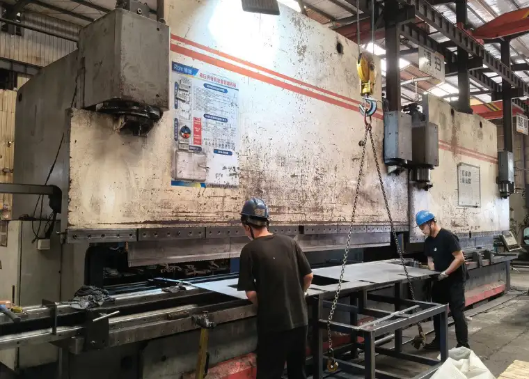
The workshop’s bending route is relevant to formed tray edges. The narrow geometry and board-support tolerances must be checked against the actual tooling.
Define what the first article must demonstrate
| Feature | Proposed check | Record to agree |
|---|---|---|
| Support height and tray twist | Locate the tray at its assembly datums and measure the individual support heights and opposite corners. Confirm the selected measuring setup can reach the inner features. | Support-height readings and the datum/support setup. |
| Insertion and fixing | Fit the nominated chassis or gauge and check travel, fixing alignment and connector approach clearance without using the connector to force alignment. | Fit checklist identifying the mating part or gauge revision. |
| Deflection under module load | Review a test using the specified mass, support span and load positions; measure movement at defined points and after unloading. | Load arrangement, readings and acceptance limits; test provision to be confirmed. |
Identify the drawing revision, measurement datums and pass/fail limits before the sample is made. The quote confirms the available measuring setup, any mating fixture and whether a specialist test needs an external provider.
Packing for your next assembly step
Protect the support faces and keep formed edges from carrying packing loads. Identify trays by drawing revision so similar server variants remain separate during assembly. State the quantity and delivery city so packing volume and the requested delivery terms can be included.
Questions before you send drawings
When should support heights be checked?
Check the formed tray before reinforcement hides the features, then verify the finished support geometry after joining and surface treatment. The agreed report identifies the measurement datums and individual support positions.
Can the tray fit different GPU server configurations?
Each tray is made to its approved board and chassis interfaces. Provide the configuration drawing or revision for each variant rather than assuming one tray fits every server.
What should I send for the drawing review?
Send the dimensioned PDF, available STEP/DXF/DWG files and assembly view. Include material, finish, quantity, delivery city and drawing revision. Mark the features in the inspection plan that control acceptance.
Can we approve a sample before ordering repeat quantities?
Request a sample or pilot batch with the agreed dimensional report and any mating checks. Scope, timing and test provision are quoted after review; repeat supply follows the accepted drawing revision and any agreed sample changes.
Discuss your GPU carrier tray
Send the part and assembly drawings with your quantity and required delivery condition. Highlight the interfaces and checks listed above that matter to your order.
Attach files in your email application. To arrange file transfer first, use the enquiry form.