
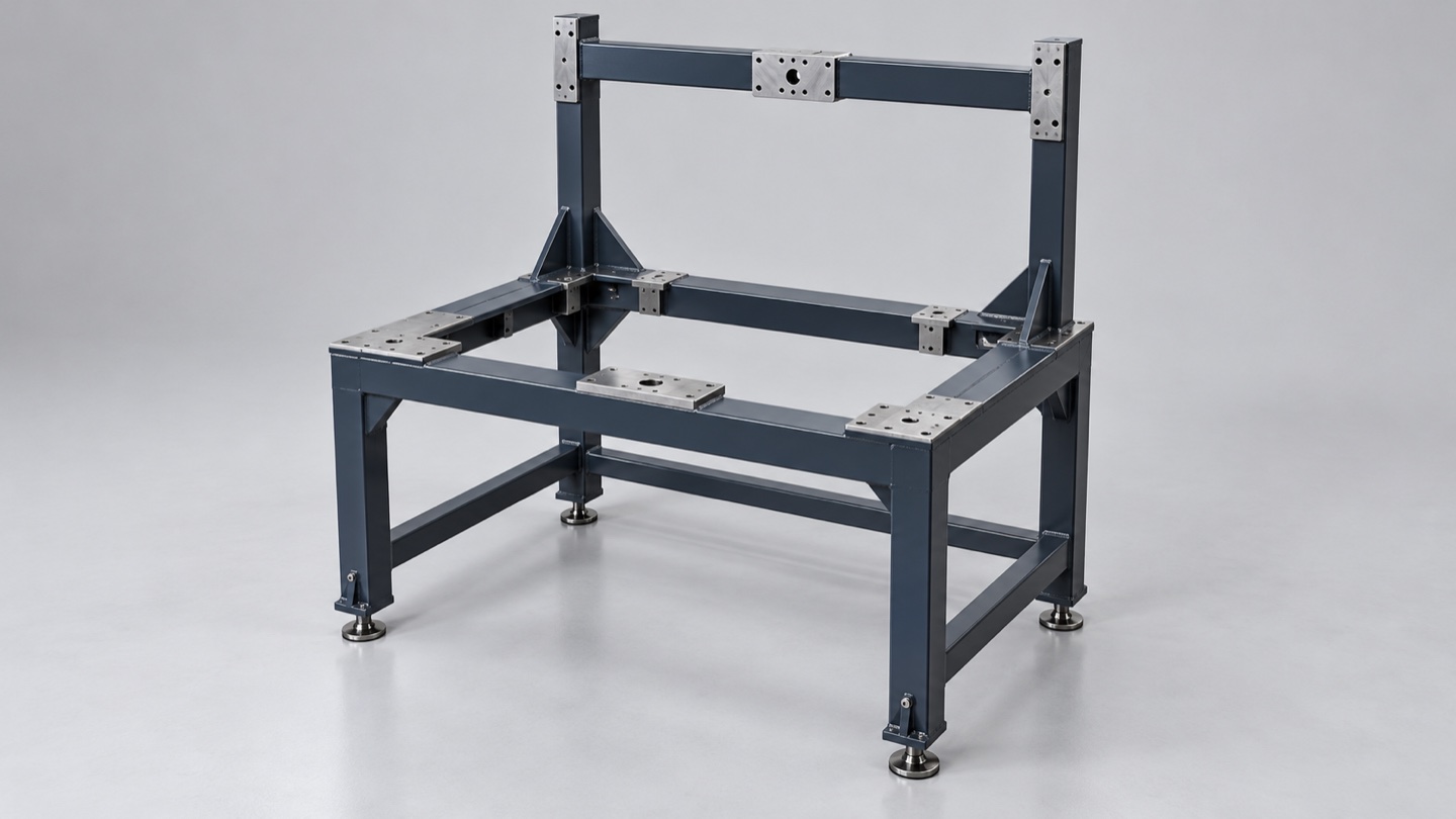
Where the machine vision inspection frame fits
Mechanical structure for an industrial vision station
Commission a custom machine-vision inspection frame for AI-assisted industrial inspection or battery assembly checks. REALJET fabricates the station structure and machines drawing-defined camera, workpiece-fixture and conveyor interfaces. The equipment designer sets their positions; optics, software and inspection accuracy remain part of the vision-system scope.
Battery assembly inspection stations
Where a battery-equipment builder uses vision to check assembly or visible defects, the frame can be reviewed against that station layout. Part presentation, camera working distance and access for fixture changes determine the mounting positions. Any dry-room, cleanliness or restricted-material requirements must be stated for the actual process.
Specify the part and delivery condition
The welded station frame, specified camera-support mounting structure and fixture interfaces. Cameras, lights, vision software, guarding systems and inspection accuracy are separate.
| What you can order | Details that define the scope |
|---|---|
| Station weldment | Workpiece and conveyor layout, feet and crossmembers |
| Machined interface frame | Camera, light-support and fixture datums |
| Separate optical support | Customer-approved isolation and mounting arrangement |
Manufacturing around your mounting interfaces
Resolve the optical and moving structures
Review camera and light locations together with the conveyor and actuator loads. The equipment designer decides whether the optical support shares the moving structure or is mechanically separate. Cut and locate members to that approved arrangement.
Control the weldment before interface machining
Weld in the fixture, measure distortion and review stability requirements. Agree any stress-relief treatment before rough and finish machining of camera, fixture and locating faces.
Finish without changing the optical contacts
Protect machined contacts through coating and cleaning. Fit any approved isolation hardware separately included in the order. Trial-fit camera and fixture templates and check locking and tool access.
REALJET combines plate cutting, bending, welded fabrication and specified milling/boring operations for approved equipment drawings. The quotation confirms the material, usable machine envelope, tooling and inspection setup for your part. A required external operation is identified before manufacture.
Agree the first-article inspection plan
| Feature | Check to agree | Record for acceptance |
|---|---|---|
| Camera-to-workpiece geometry | Relative positions of camera mount, fixture datum and conveyor | Dimensional report in defined support condition |
| Fixture changes | Mechanical location after repeated removal and refitting | Agreed repeat-assembly check |
| Dynamic and thermal behaviour | Specified motion cycle, acceptable displacement and environment with the actual optical setup | Customer-led image stability test; no inferred recognition rate |
Mark the drawing revision, datums, inspection limits and measurement support condition before the sample is made. The measuring method and available instruments must suit the feature and tolerance; confirm any specialist measurement or test provision in the quotation.
Approve the sample or pilot batch against the agreed results before repeat supply. Record accepted changes in the drawing revision and inspection plan.
Protect the interfaces during delivery
Agree packing supports, protection for machined contacts and threads, and identification for any mating sections. Send the quantity, destination and required shipping terms so packing and freight scope can be included in the quote.
Questions before you order
Can the frame guarantee AI inspection accuracy?
No. The mechanical interfaces can be manufactured and inspected to drawing. Image accuracy also depends on the optics, lighting, movement and software and requires whole-station validation.
Can the camera support be separate from the conveyor?
Yes, where the approved design uses separate supports. Provide their relative datums, floor connection and any isolation requirements for the manufacturing review.
Send your machine vision inspection frame drawings
Camera/light layout, working distance, workpiece fixture, conveyor envelope, motion loads and the customer-defined stability and environmental acceptance criteria.
Include the dimensioned PDF, assembly view, available STEP/DXF/DWG files, bill of materials, material and finish, quantity, drawing revision and destination. Identify the interfaces and first-article checks that control acceptance.
Attach files in your email application. For confidential files, use Enquiry to arrange the exchange method first.
Explore Battery manufacturing, energy storage, EV charging and solar components →