
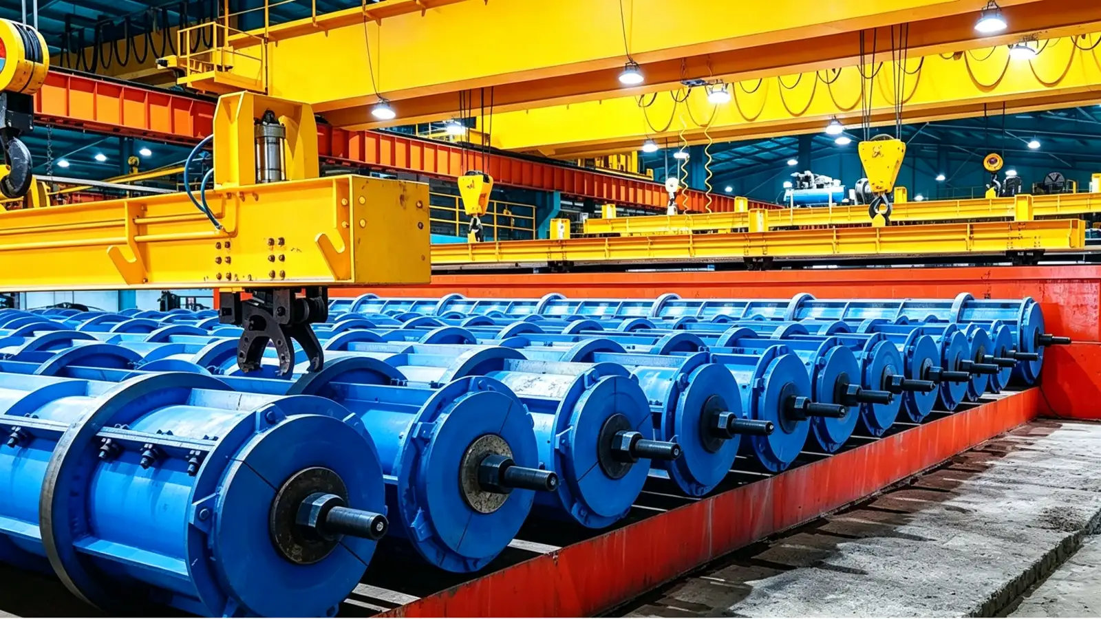
The cage is one part of the pile-end assembly
A spun pile cage is built from longitudinal bars with spiral wire welded around them to form a rigid cylinder. That cage is only one part of what sits inside the mould. At each end, an end plate carries the pile joint, and a steel skirt formed around the plate prevents grout loss and adds confinement at the pile head. The cage, the end plates and the skirts are assembled as one set before the mould is closed, and their fit decides whether tensioning and spinning behave as designed. A loose or misaligned part at this stage becomes a structural problem at the head of the driven pile, where the joint takes the full impact of the hammer.
The pile geometry comes from the governing standard. GB/T 13476-2023 sets the dimensions and reinforcement requirements for pretensioned spun concrete piles in China, and EN 12794 does the same for precast concrete foundation piles in Europe. The end plate hole pattern, the cage diameter and the skirt size all trace back to that drawing, so the assembly step is where the standard meets the steel. Getting those numbers right before loading is far cheaper than correcting a mismatch after the pile is spun.
The cage must fit the mould and the end plate
The cage welding machine positions the longitudinal bars and welds the spiral to form the cage. Its diameter, usable length, bar count and spiral pitch are fixed by the cage drawing, and those same numbers decide whether the cage drops into the mould with the right concrete cover and lines up with the end plates.
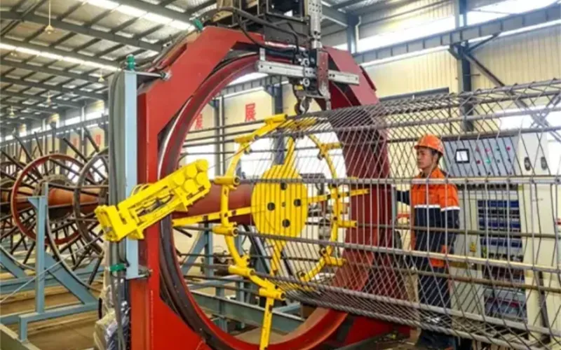
Cage Welding Machine for Spun Concrete Piles
The cage welding machine forms the cylindrical reinforcement cage, so its diameter, length and spiral pitch must match the pile drawing and fit the mould and end-plate interfaces.
View equipment detailsEnd plate accuracy is the other half of this fit. The plate hole pattern must match the PC bar or strand layout so the tendons pass through and anchor as the design intends. A plate that is flat and drilled to the wrong pattern, or a cage whose bar positions drift, produces an interface mismatch that shows up at tensioning, not at welding. The common failure modes in spun pile production include end plate mismatch and cage accuracy problems, and both are cheaper to prevent at the drawing stage than to find on the floor.
The skirt is formed to the end plate
The skirt is a rolled steel band fixed around the end plate. A skirt forming machine shapes the strip into the skirt profile that matches the pile diameter and the approved end assembly. The forming geometry is selected to fit the plate and the pile, and the strip width, thickness and grade are part of that selection.
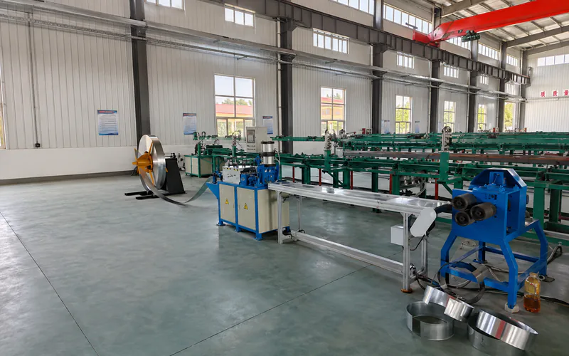
Skirt Forming Machine for Spun Pile End Assemblies
The skirt forming machine shapes the steel skirt that fits the pile end plate, so its profile and diameter must match the approved end assembly and pile geometry.
View equipment detailsSkirt forming is not the same as end plate manufacture. The machine makes the skirt; end plate production, hole preparation and the joining of skirt to plate are separate operations whose inclusion must be stated in the equipment package. One machine does not cover the whole end assembly, and assuming it does leaves a step unnamed and unbudgeted. Where several pile diameters share the line, the size range and tooling changeover must be checked against that range rather than assumed to suit every size.
Assemble and load as one set
At the mould-loading station the end plates, with their skirts attached, are placed at the mould ends, the cage is positioned inside, and the split mould is closed. The mould then carries this assembly through prestressing, centrifugal spinning and curing, so every interface fixed here has to survive those stages. Lifting points and end connections on the mould must suit the loaded assembly, not just the empty shell. The closed mould is then moved to the tensioning and spinning stations, so an assembly that shifts during handling repeats the error through every later stage.
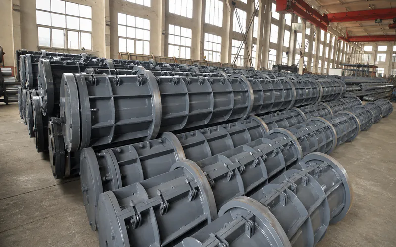
Steel Mould for Prestressed Spun Concrete Piles
The split steel mould carries the assembled cage, end plate and skirt through tensioning, spinning and curing, so its diameter and end connections must suit the assembly.
View equipment detailsGetting the assembly right before closing the mould protects the later steps. If the cage sits off-centre, the wall thickness varies after spinning. If the end plate does not match the tendons, tensioning cannot be applied cleanly. If the skirt does not fit the plate, grout leaks at the head. None of these faults is visible from outside the mould until the pile is opened, which is why the assembly check belongs before loading, not after.
What to confirm before ordering
Bring the pile drawing, the cage schedule and the end plate and skirt specifications to the equipment discussion. State the diameter and length range, the bar and wire sizes, the spiral pitch and the end assembly the line must produce. Ask the supplier to confirm that the cage welding machine, the skirt forming machine and the mould are matched to that drawing and to each other.
With those inputs, review the spun pile production line planning page and treat the cage, end plate and skirt as one assembly chain rather than three separate buys. Matching them to the pile drawing before ordering prevents the end-plate mismatch that disrupts production later.