
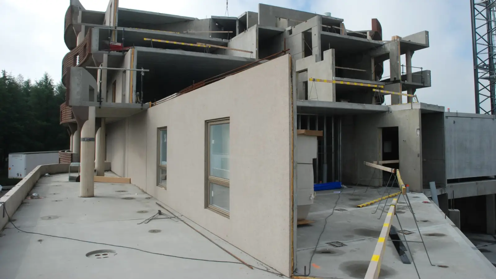
What the mould has to form beyond the panel outline
A wall panel is rarely a plain rectangle. The mould forms the outline, the thickness and the face finish, and then it forms everything that passes through the panel or is embedded in it: window and door openings, sleeves for services, boxouts for brackets and base plates, and cast-in items such as threaded bars, anchor plates, conduits and lifting inserts.
Those features are usually the reason a panel enquiry is difficult. The panel outline is drawn once, but openings and inserts come from several consultants and arrive at different times, at different levels of detail. The Hong Kong Buildings Department code of practice for precast concrete construction puts the requirement plainly: recesses, sleeves and boxouts should be formed from a suitable material, and their shape, size and location should be identified on the precast unit shop drawings. If they are not on the shop drawing, they will not be in the mould.
Realjet engineers project-specific steel moulds around the approved component geometry for the precast concrete mould range, and openings and embedded items are part of that review rather than an afterthought.
Shop drawings, then the mould drawing
The sequence matters more than the drawing format. First the shop drawing for the panel, showing geometry, reinforcement, openings and cast-in items together. Then the mould drawing, which turns those features into formers, blocks, fixing plates and setting-out marks. Then the former and insert schedule, which is what the mould shop actually builds from.
The code is specific about two practices in this sequence. Templates should be used to fix threaded bars, bolts, inserts, sleeves and base plates during production, so a row of items is positioned as one assembly rather than one at a time. And where a connection system demands tight tolerances, mock-up elements should be produced before mass production begins.
A practical rule follows. Send opening and insert information as a schedule with coordinates and tolerances, not as a mark on an architectural elevation. Our note on the wall panel mould RFQ inputs covers the rest of the enquiry package.
Fixed formers and removable boxouts
A feature that repeats on every panel is normally formed by a fixed former built into the mould: a welded steel frame for a window or door opening, a tube or block for a sleeve, a plate assembly for a recess. A fixed former holds position without relying on the pouring crew, so it is preferred wherever the quantity justifies it.
Removable formers are used where one mould has to produce variants, or where a large former has to come out before the panel can be stripped. They need location features such as pins, dowels, stops or captive bolts that put them back in the same place every time; a former that is simply dropped into position will drift.
Two details decide how a former behaves at stripping. The first is draft. Even a shallow taper on the side faces removes the suction and the edge damage that a parallel face produces. The second is the corner treatment. A sharp internal corner in the concrete is a stress raiser, and openings are generally detailed with a chamfer, a radius or trim reinforcement for that reason. The mould forms whatever the detail shows, so the detail has to be settled before the former is made.
Where a window or door frame is cast in, a limit device on the mould should hold it in position for every unit, and the frame becomes a supplied item with its own tolerance. Sandwich panel moulds add a further complication, because the opening passes through the insulation layer as well as the two concrete wythes.
Position tolerances to write into the enquiry
Tolerances for these features come in two families, and they should not be mixed. One governs the position and size of the opening or the embedded item in the finished panel. The other governs the mould that produces it. The code sets out the relationship between them: manufacturing tolerances should be specified for overall dimensions, thickness, bow, twist, flatness, squareness, and the size and location of openings and cast-in items, and the mould tolerances should be compatible with the construction and erection tolerances so that the finished element still fits on site.
Lifting devices are the clearest example. For a wall or facade panel, the same code gives recommended location tolerances of about 25 mm in the face in any direction, about 5 mm on the edge across the thickness and about 25 mm on the edge along the length. Lifting positions are generous in the plane of the panel, because a lifting point only has to line up with the clutch, and tight across the thickness, because the insert has to sit at a known depth. Reporting one number for all three directions would be wrong.
Embedded items that transfer load behave differently from lifting points. A threaded bar or a base plate that carries a connection has to line up with a matching item in the adjacent element, so its tolerance is driven by joint fit, not by the lifting equipment. Those items should be identified in the schedule as connection items, with a tighter tolerance and a stated reference point.
One more rule belongs in the enquiry: state the reference the tolerance is measured from. A single working point or line, defined once on the mould drawing, removes most setting-out arguments.
Fixing inserts and sleeves so they do not move
Concrete placement moves anything that is not fixed. The code's guidance on lifting inserts applies to everything embedded: inserts should be firmly fixed to the mould in a way that prevents movement during concrete placement, and they must be cast in at the correct height to engage the lifting clutch, hook or shackle that will handle the panel.
Three points follow from that. The recess former and the insert have to be compatible, because a former designed for one insert type will not hold another at the right depth. Formers take punishment over a production run, so they have to be inspected and maintained instead of used until they fail. And proprietary lifting inserts are a supplied component with their own rated capacity and instructions, so the type used should be agreed between the producer and the party that will lift the panel, because the insert chosen for factory handling may not be the one needed on site.
Sleeves follow the same rules and add a schedule problem: services are often designed later than the structure, so a panel may be released for production with sleeve positions still provisional. Agree in the contract how a late change is handled, and whether it is a mould modification or a site-drilled hole.
Demoulding, cracking and production reality
An opening changes how a panel behaves during stripping. Concrete shrinks onto a former, and the faces around an opening are restrained on two or more sides, so its corners are where damage usually starts. Correctly tapered formers and a release agent applied as directed reduce suction and friction, and the code notes that the agent must not discolour the face or reduce the adhesion of later finishes.
Openings also slow the cycle. Setting out, fixing and checking formers takes longer than casting a plain panel, and stripping takes longer too, so mould occupancy rises and the number of moulds needed for a daily output rises with it. Trial units are the accepted way to prove the details before a run starts, since several adjustments are normally needed.
Moulds also wear. The code recommends a full dimensional re-check after roughly 100 castings, and formers and insert fixings are the parts most likely to drift, so they belong in that check.
Mould count, repeated use and the cost of a bespoke panel
Every opening, sleeve and embedded item adds a former, a fixing detail and a setting-out check. A panel with two windows, four sleeves and six inserts is a much slower item to produce than a solid panel of the same size, and its mould is more expensive to build and to maintain.
Quantity decides whether that cost can be spread. The code makes the point that a bespoke steel mould for a facade panel is normally only economical at around 200 or more identical panels, which is a useful threshold to keep in mind when a project is considering a unique panel for a short run.
Where a building repeats the same opening pattern over many floors, one mould serves the whole job and the formers are set once. Where the pattern changes floor by floor, the mould needs adjustable formers or the project needs several tools.
What to send with the mould enquiry
The buyer's design authority owns the opening schedule, the structural trim around each opening, the insert types and their rated capacities, and the face finish. The mould supplier owns how those features are formed, positioned and released.
A complete package for the opening and embedded item scope contains:
- The opening schedule, with size, position, reference datum and tolerance for each opening
- The type of each former, or the requirement that the supplier selects it
- The insert and sleeve schedule, with type, depth, orientation, rated capacity and the party that supplied it
- The reveal depth and edge detail for each opening, including chamfers and trims
- Which items are for factory handling and which are for site lifting
- The face finish, and any surface that must stay unmarked
- The product standard the panel is made to, such as EN 14992 for wall elements
The wall panel family sits inside the building component mould category, and the steel mould system for wall panels is the product reference for this type of enquiry, covering fixed, movable and hydraulic arrangements. The catalogue page is a starting point: the mould is developed around the approved panel geometry and the production arrangement, and the openings and cast-in items are part of that geometry.
Next step
Before you ask for a quotation, freeze the opening and insert schedules and mark which items are connection items rather than handling items. State the reference datum and the tolerance for each one, and name the finish that must be protected around the openings. With that package a mould supplier can design the formers, fix the inserts reliably and confirm the mould count that the daily output actually needs, and can tell you which changes would still be possible after the mould is built.