
What a sandwich panel mould must hold
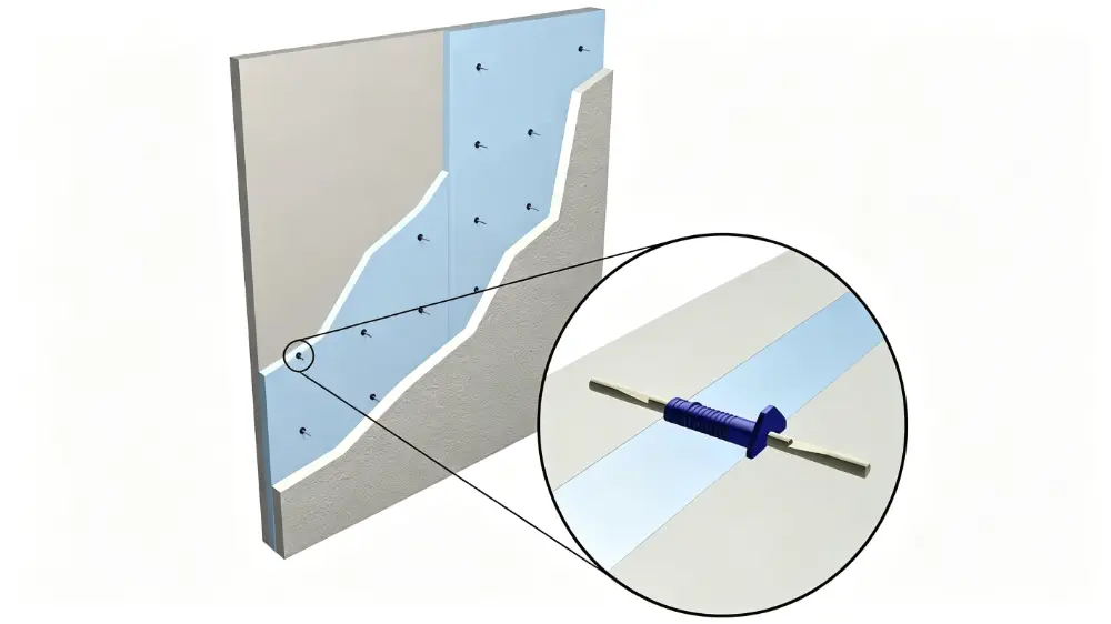
A precast concrete sandwich wall panel has two concrete wythes separated by a rigid insulation layer and tied together with shear connectors. The mould has to locate all three layers and the connectors so the finished panel meets the drawing. A buyer who sends only a panel size gets a mould that may not hold the insulation or the connector pattern the project needs.
The precast concrete moulds range includes the Building Component Moulds category, where wall panel systems sit. The wall panel mould product page is the reference for the configurations Realjet can engineer.
Casting direction sets the faces
Decide which face is cast down. Most plants cast the architectural outer face down on a flat steel table so the mould controls that surface directly, then build the inner wythe and insulation on top. Casting the structural face down reverses which surface the mould forms. The choice drives the contact plates, the demoulding plan and the face that becomes the exposed finish, so state it in the RFQ.
Insulation layer and continuity
The insulation sits between the wythes as a continuous layer, commonly expanded or extruded polystyrene, with polyurethane or phenolic foam used where higher R-values are required. The mould must hold the insulation in place and keep it from shifting during concrete placement. Gaps or compression at the edges break the thermal line, so the buyer should specify the insulation thickness, the material and the allowed tolerance, and confirm how the mould maintains continuity at panel edges and openings.
Shear connectors and thermal bridging
The two wythes are tied by shear connectors that carry load across the insulation. Steel connectors are strong but conduct heat, which creates a thermal bridge. Fibre-reinforced polymer or composite connectors cut that bridge but need verified load data. Connectors may be discrete pins or continuous trusses, and the panel is designed as composite, where both wythes act as one section, or non-composite, where they are tied only for stability. The mould must position the connectors to the approved schedule, clear of reinforcement and lifting anchors, so the buyer should supply the connector layout, not leave it to the supplier.
Double-face finish and tolerances
Because both faces are formed by the mould, the finish on each is a mould responsibility. An exposed architectural face needs defined blowhole limits, colour uniformity and joint lines, while a face that will be covered needs far less. Tolerances for precast panels are set by references such as ACI ITG-7, EN 14992 for wall panels and PCI MNL-128 for plant quality. State the standard and the tolerance class for each face so the supplier knows which surfaces to control. Where the two faces have different finish classes, the mould may need separate surface treatments on each form, and the supplier should state which face each treatment applies to.
Openings, embedded items and casting sequence
Window and door openings, lifting anchors, conduits and insulation need fixed positions in the mould. The casting sequence follows from the build-up: place the first wythe concrete, set the insulation and connectors, then place the second wythe, or cast the outer face down and build upward. The sequence decides which inserts are fixed before concrete and which are formed openings. The RFQ should list each item, its position and the supplier's responsibility for holding it.
Sizing the mould to the panel and the crane
Sandwich panels are larger and heavier than solid wall panels of the same footprint, because the insulation adds thickness without adding much strength until the concrete cures. The mould has to provide lifting anchor positions that suit the full composite weight, not just one wythe, and the buyer should confirm the rated capacity with the supplier. Long panels also need the mould to hold flatness across the span, so the table or form rigidity is part of the specification, not an afterthought.
Design inputs for the RFQ
Prepare the panel drawing with wythe thicknesses, the insulation specification, the connector schedule, the finish class for each face and the joint details. The mould is built from that package, so the more complete the drawing, the closer the quotation is to the real tool. Realjet engineers wall panel moulds around the approved panel geometry and the factory process, and final dimensions, functions and delivery scope are confirmed through the buyer's project documents.
The connector schedule is the part most often left vague. State the connector type, the spacing in each direction, the embedment into each wythe and the load class the panel design assumes. Where the project cites a thermal performance target, confirm that the chosen connector and insulation combination meets it, because a steel connector that breaches the insulation can pull the whole panel below the required R-value.