
The number nobody puts in the enquiry
Ask a mould supplier for a wall panel mould and the conversation moves to cavity size, panel thickness, openings, finish and price. Weight usually arrives later, as a line on the general arrangement drawing, after the plant layout and the crane have already been chosen.
That sequence is backwards. The weight of a mould decides which crane serves the casting area, how many lifting points the mould needs, whether it can be turned or stripped in one piece, and whether it fits on a truck. All four are capital decisions taken before the mould order is placed, and all four are hard to change afterwards.
For a precast line buyer, the useful move is to put a weight limit and a handling concept into the enquiry, and let the mould design work inside those constraints.
Weight is a design output, not a specification
A mould is a steel structure sized for stiffness, concrete pressure and wear. Its weight follows from those requirements, and the supplier cannot simply declare a lighter one without changing plate thickness or the rib layout.
What the buyer can do is set a ceiling. A plant with a 10 t overhead crane cannot accept a 12 t mould, however good the mould is. Stating the crane capacity, the hook height and the available lifting points in the enquiry lets the supplier design to the site rather than to an ideal.
The same applies to the floor. A mould that stands on a casting bed, or on a tilting table, puts its weight through a small number of contact points. The slab has to be designed for that, and the bearing points are part of the mould design.
What makes a mould heavy
Four items account for most of the variation between two moulds of the same cavity size.
Plate thickness at the casting face is the first. It is set by the concrete pressure and by how much deflection is acceptable over the panel. A deep wall panel poured in one lift pushes harder than a thin slab, and the face plate grows accordingly.
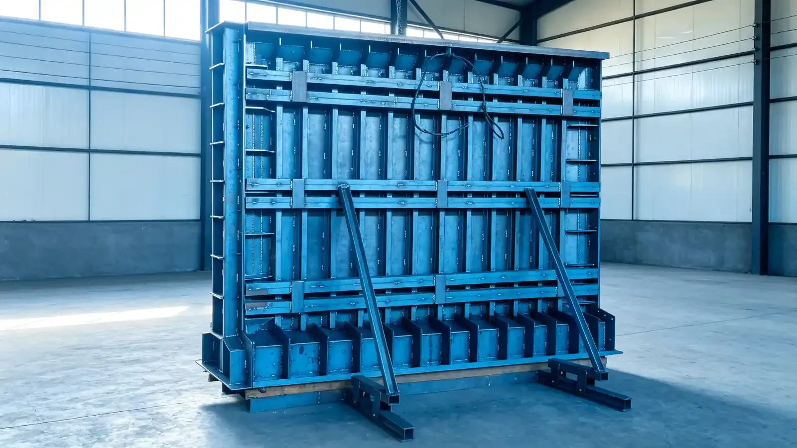
The backing structure is the second. Ribs, frames and stiffeners exist to keep the face flat under load, and their depth matters more than their number. A supplier who adds ribs instead of deepening them adds weight without adding much stiffness.
Hydraulics and mechanics come third. A mould with powered side forms, hydraulic rams and a travelling carriage carries the cylinders, the power pack and the control panel. On a large panel mould that can be a significant share of the total.
Insulation, cladding and heating, where the plant needs them, come fourth. A mould that must keep concrete warm in a cold hall is a different object from a bare steel one.
Lifting points decide how the mould behaves in the air
Four lifting points do not automatically give a stable lift. What matters is where they are, relative to the centre of gravity, and what angle the slings make.
On a tall panel mould the centre of gravity sits high, and a lift from four points near the top will hang the mould vertically but leave it free to rotate about the vertical axis. Two points on the fixed half and two on the moving half is a common arrangement, and it means the two halves can be lifted separately when the mould is opened.
The safe practice is to design the lifting points with the sling angle stated, not just the load. A two-leg sling at 30 degrees to the horizontal puts the full mould weight on each leg, because the vertical component of each leg is only half the total. At 45 degrees each leg carries about 71 percent of the weight, and at 60 degrees about 58 percent. A lift that looks gentle on a drawing can double the load in a lug if the angle is wrong.
EN 13155 covers non-fixed load lifting attachments for cranes, including lifting beams and C-hooks, and requires proof of static strength, elastic stability and fatigue strength. A spreader beam used to keep slings vertical on a wide mould falls inside that scope. The lugs welded to the mould do not, because they are part of the mould, and their design is the mould maker's responsibility.
Crane capacity is not the only crane question
A crane rated for the mould's weight may still be the wrong crane. Two further questions decide whether it works in practice.
The first is hook height and coverage. A tall panel mould lifted from a casting bed needs clearance for the mould, the slings and the hook block. A plant designed around a low gantry can find itself unable to stand a mould upright, even though the load is well within the rating.
The second is duty. A mould is lifted several times per cycle, every working day, for years. That is a different duty class from a maintenance crane used twice a week, and the classification systems in ISO 4301-1 and the FEM rules express the difference. A crane specified for occasional use will wear out early on a production line.
Stripping, turning and loads that are hard to model
Demoulding is where moulds are damaged. Concrete grips the face, the stripping force is applied at the lifting points or at the stripping lugs, and the mould is often twisted as it comes away. A mould designed only for a vertical lift from four symmetric points can be overloaded during stripping, when the load is uneven and partly horizontal.
The same applies to turning. A wall panel mould that rotates from horizontal to vertical, or a mould that is flipped to release a panel, passes through positions where the load path is nothing like the static case. Suppliers who design for this build in turning trunnions, dedicated stripping points and a stated sequence.
The enquiry should ask for that sequence in writing: which points are used for lifting, which for stripping, which for turning, and what the permitted sling angles are at each step.
Transport sets a hard limit
A mould that is 3.2 m wide cannot travel on a road that allows 2.5 m without a permit, a pilot vehicle or a redesign. On long moulds the same argument applies to length, and on tall erected moulds to height.
The practical answer is a bolted or pinned split at a joint that does not compromise the casting face. That split then has to be reassembled and checked on site, which is a commissioning activity with its own tolerance.
Buyers should state the transport limits for the destination country in the enquiry, and ask how the mould is split, how the joint is located and how the alignment is verified after assembly.
What the enquiry should contain
| Item | What to state | Why it matters |
|---|---|---|
| Maximum mould weight | A ceiling set by the crane | Prevents a design that cannot be handled |
| Crane capacity, class and hook height | Rating at the working radius, plus duty class | Sets what the plant can lift and how often |
| Lifting and stripping points | Number, position and rated load per point | Defines the handling sequence |
| Sling angles | Permitted angle at each lift | Load per lug depends on it |
| Spreader beam | Whether the supplier provides one, and to which standard | A non-fixed attachment under EN 13155 |
| Turning or rotating requirement | Which operations the mould must perform | Adds trunnions and changes the structure |
| Transport limits | Width, height, length and weight for the route | Forces the split positions |
| Assembly on site | Who assembles, who checks alignment, what record | Mould joints affect the casting face |
Evidence to ask for
Ask for a weight report itemised by major assembly, so the buyer can check the sum against the crane. Ask for a lifting point schedule, with each point marked on the mould and its rated load on a plate, and for a load test record of the assembled mould, witnessed before shipment, which proves the points and the structure together.
On a mould with a transport split, add the reassembly alignment record. It is the only evidence that the mould arrived in the geometry it was tested in.
Who owns what
| Decision | Owner | Why it sits there |
|---|---|---|
| Crane capacity and duty class | Buyer | Part of the plant capital scope |
| Mould weight ceiling | Buyer, agreed with supplier | A handling constraint, not a mould property |
| Lifting point design and rating | Supplier | Part of the mould structure |
| Lifting beam or spreader | Buyer or supplier, stated in the order | It is separate equipment with its own standard |
| Stripping and turning sequence | Supplier proposes, buyer approves | Ties the mould to the plant operations |
| Transport split and route limits | Buyer provides limits, supplier designs the split | Both sides hold half the information |
| Site reassembly and alignment check | Agreed at order stage | Often falls between two contracts |
Where to take the question
Weight and handling are cheap to discuss at enquiry stage and expensive to correct after the crane is bought. A buyer who brings the crane rating, the hook height and the transport limits to the first meeting gets a mould that fits the plant instead of a plant that has to be adapted to the mould.
Realjet designs and manufactures project specific steel moulds, with lifting points, stripping sequence and transport splits agreed against the plant layout. The precast concrete moulds overview shows how the families are organised, the building component moulds category covers the tall, heavy moulds where handling dominates the design, and the wall panel moulds page is the clearest example of a mould whose weight decides how the whole casting bay is equipped.