Why the mould and spinner are a pair, not two items
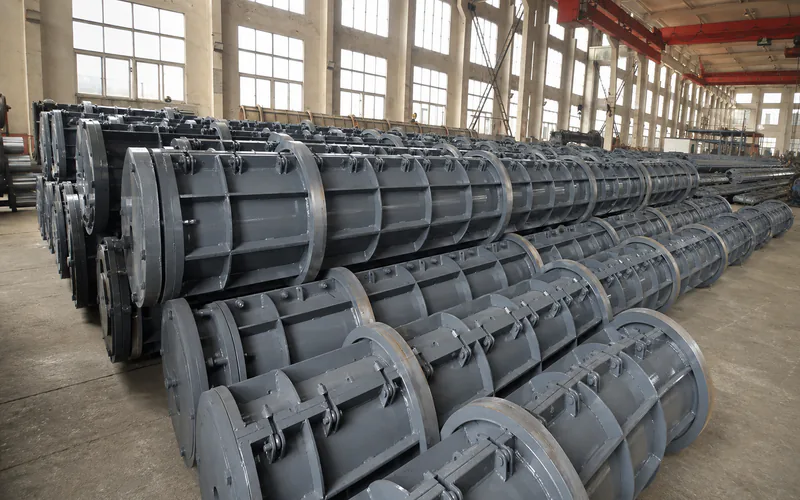
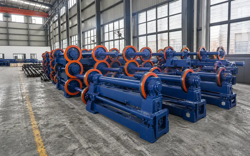
The steel mould and the centrifugal spinning machine are bought as a matched pair even when they come from separate line packages. The mould defines the pile outer shape, and the spinner rotates it. If the running rings on the mould do not match the rollers on the spinner, the mould rides badly, vibrates at high speed and wears unevenly. The two are specified together, not picked independently and hoped to fit.
This matters because the mould also touches every other station: it is closed and bolted, charged with concrete, tensioned, spun, cured, demoulded and lifted. A running-ring or lifting-point decision made for the spinner reaches the crane, the transfer trolley and the curing pit. Confirming the interface early prevents a change that ripples through the whole line.
Running rings and roller spacing
The running rings are the hardened bands on the mould that rest on the spinner rollers. Their diameter, width and spacing decide how the mould is supported and how load transfers during acceleration. The spinner rollers must match that geometry across the full diameter and length range you plan to run, including the longest pile, because support at the ends is where long moulds are most exposed.
Confirm the running-ring profile and the roller spacing as a single specification. If you later add a diameter or a longer length, recheck the roller bed rather than assuming the existing spinner still fits. GB/T 13476-2023 sets the dimensional and quality requirements for the pile itself, and the mould that produces it has to hold those tolerances repeatedly, so the ring and roller interface is part of how the product stays in spec.
Lifting points and mould handling
A spun pile mould is long and heavy, and it is lifted at defined points when it moves between stations. Those lifting points must be coordinated with the twin-hook overhead crane or the gantry that serves the line, because the two lifting points have to clear the spinner, the curing pit and the feeding track. If the lifting arrangement is decided only at installation, the crane span or the hook spacing may not suit the mould, and handling becomes the bottleneck.
The split line of the mould, where the two halves bolt together, also affects the spinner and the closing track. The closure has to be tight enough to avoid leakage along the joint during spinning, and the bolt arrangement has to be reachable from the closing position. These are interface details, not mould-only details, because the spinner and the closing track work directly against them.
Diameter, length and the drive line
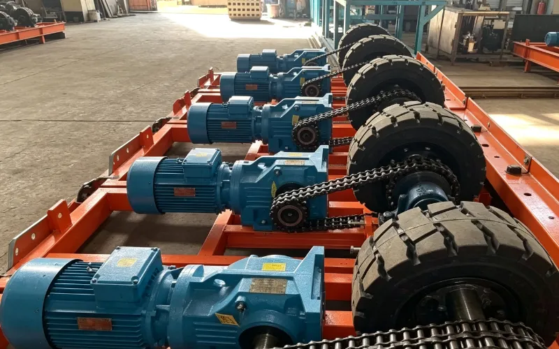
Diameter and length decide both the mould and the drive that spins it. A friction-wheel drive rotates the mould by contacting the running rings, so its force, speed and stopping points have to suit the mould mass and the route the mould travels. On a fixed spinner the drive is built into the frame. On a transfer route the drive moves the trolley and the mould together, and the stopping points must line up with the spinner and the curing positions.
State the full diameter and length range when you specify the drive, because a longer or heavier mould changes the required force and the foundation. The drive and the spinner should be quoted against the same mould data as the mould itself, so the three descriptions agree instead of being reconciled later on site.
Confirm these before you ask for a quotation
Before requesting offers, lock the items that the mould and spinner share: the running-ring profile, the roller spacing and diameter, the lifting-point layout, the split-line and bolt arrangement, and the diameter and length range. Give the same mould data to everyone quoting the mould, the spinner and the drive, and ask each to confirm compatibility in writing.
Also confirm who owns the interface drawings. The mould supplier, the spinner supplier and the handling supplier each have a stake in the running rings and the lifting points, and a single agreed drawing prevents the common situation where every party assumes the other allowed for it.
Where the interface sits in the line
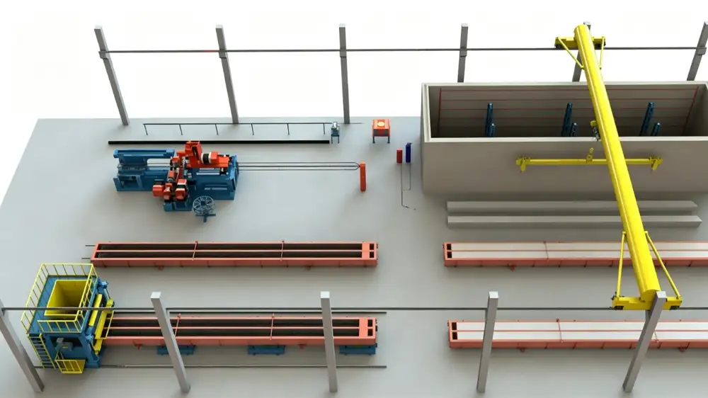
The mould and spinner sit between concrete charging and steam curing. Their interface has to work with the feeding method on one side and the curing pit on the other, because the same mould travels the whole route. A spinner that fits the mould but not the transfer trolley, or a mould whose lifting points do not suit the crane, will stall the line at exactly the point you least expect.
For project preparation, review the spun pile production line planning page and send your pile drawings, the mould dimensions and the handling layout. Treat the mould, the spinner and the drive as one coordinated specification, and the rest of the line will follow from it.