
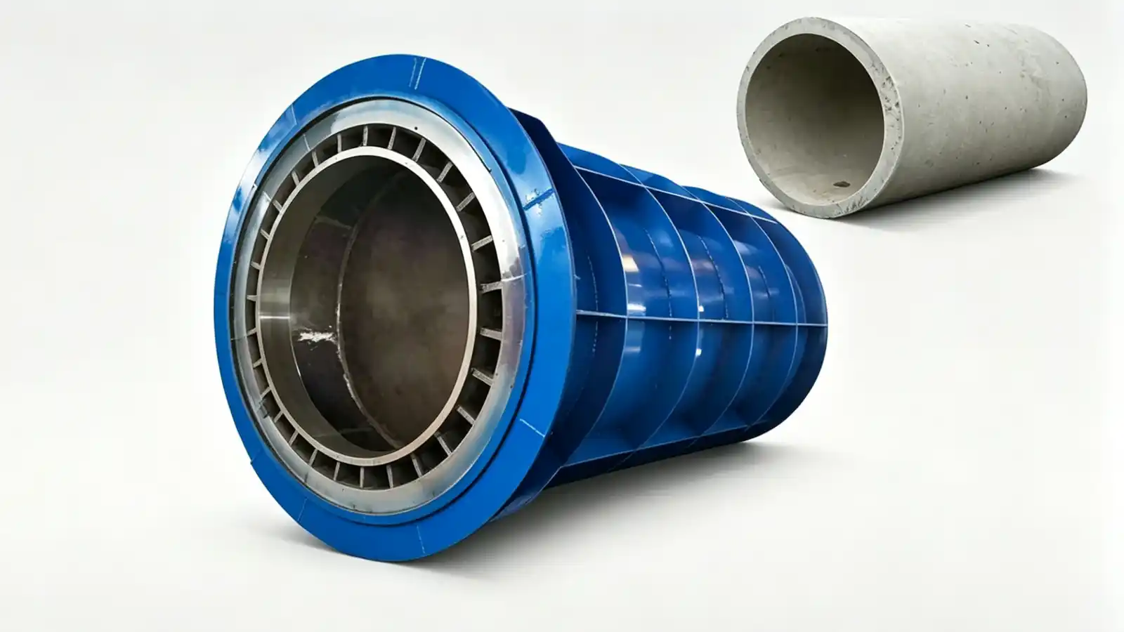
What the mould has to produce
A concrete pipe mould is the reusable steel tool that forms drainage, sewer, storm-water and utility pipes. The pipe dimensions, joint profile, wall thickness, reinforcement arrangement and the chosen production method decide the mould concept. A buyer who sends only a nominal diameter gets a quotation that assumes a pipe the mould may not actually be able to make. The RFQ should start from the finished pipe specification and work back to the tool.
Concrete pipe moulds sit within the precast concrete mould range under the Municipal Infrastructure Moulds category. The published concrete pipe mould page is the product reference for this family. The mould enquiry is a project-specific review of geometry, cycle and handling; the catalogue page is a starting point, not a specification.
Diameter, class and the standard that governs the pipe
Concrete pipe is purchased and inspected against a strength class, not against a drawing alone. ASTM C76, the specification for reinforced concrete culvert, storm drain and sewer pipe, defines five classes, I through V, with increasing reinforcement and load capacity. The class sets the wall thickness, the reinforcement and the joint requirements that the pipe must satisfy. The mould has to be built so the produced pipe can meet the selected class under the project's approved concrete mix and release condition.
Pipe diameters in practice range from about 150 millimetres to 3000 millimetres. Smaller pipes are often produced horizontally in a spinning process; larger diameters are more commonly cast vertically. The diameter range and the class schedule should be stated explicitly, because they drive the mould size, the core concept and the handling equipment.
Choose the production method before the mould
The production method decides how the mould is loaded, consolidated and stripped. Common methods include:
- centrifugal spinning, where the fresh concrete is compacted by rotation in a horizontal mould, used for many standard drainage pipes;
- roller suspension (roller method), where a rotating mould rides on rollers and compaction comes from both rotation and a roller path;
- vertical casting with vibration, where concrete is placed and vibrated in an upright mould, suited to larger diameters and short runs;
- pressed methods, where pressure consolidates the concrete in the form.
Each method needs a different mould interface. A spinning mould must be balanced and sealed for rotation. A vertical-cast mould needs a stable core and a clean demoulding path. The RFQ should name the method so the supplier designs the tool around the real process instead of a generic cylinder.
Inner core, outer shell and joint geometry
Most concrete pipe moulds use an inner core and an outer shell. The core forms the pipe bore; the shell forms the outside. The gap between them is the wall, set by the pipe class. The joint profile (socket and spigot, flat band, or a gasket groove) is machined into the end forms, because the joint decides whether two pipes seat and seal in the trench. Joints for buried pipe commonly follow ASTM C443 for rubber-gasket joints in concrete pipe, or ASTM C361 for reinforced concrete low-head pressure pipe.
The end forms carry the socket, the spigot and any gasket groove. These are project-specific and should be built into the end form rather than cut on site. If the joint standard and the groove geometry are not stated, the supplier guesses the sealing detail, and the pipe may not mate with fittings already specified for the project.
Demoulding clearance, cycle and trial assembly
Demoulding clearance is the space the core needs to withdraw without striking the fresh concrete. It depends on the pipe diameter, the wall taper, the socket geometry and the reinforcement near the ends. If the clearance is too tight, the core drags on the bore and damages the pipe. The RFQ should give the internal profile and the permitted taper so the core can be designed for a clean pull.
Mould quantity follows the target output and the time each mould stays occupied: core preparation, reinforcement placement, closure, concrete placement, curing, opening, lifting, cleaning and inspection. A cycle that ignores cleaning and inspection understates the mould count. For several pipe sizes, list the quantity of each and the casting sequence.
Trial assembly is the check that the workshop-built mould forms the approved geometry and releases the pipe cleanly before shipment. The trial records should include dimensional checks against the approved drawing and a pull test of the core. A buyer who skips trial assembly buys the right to find fit problems on the production floor.
What to send with the RFQ
A useful concrete pipe mould enquiry package includes:
- authorised pipe drawing, diameter schedule and class (for example ASTM C76 Class III);
- joint standard and groove geometry, with gasket reference where fixed;
- wall thickness, reinforcement arrangement and lifting inserts;
- production method (spinning, roller, vertical cast or pressed);
- target accepted output, working calendar and mould quantity basis;
- approved concrete release condition and the standards the pipe must satisfy;
- dimensional and surface acceptance requirements;
- preferred mechanical or hydraulic operation where already decided;
- required workshop assembly, inspection, documents and delivery scope.
Ask each bidder to list every assumption and deviation. The proposal should distinguish mould supply from concrete equipment, curing systems, cranes, installation work and production support. Realjet reviews project-specific concrete pipe moulds from the approved pipe geometry and the production plan; send the diameter schedule, the class, the joint standard, the required output, the drawing status and the handling concept through the precast concrete mould enquiry route so the response addresses the correct municipal infrastructure mould and the boundary for the specific project.