
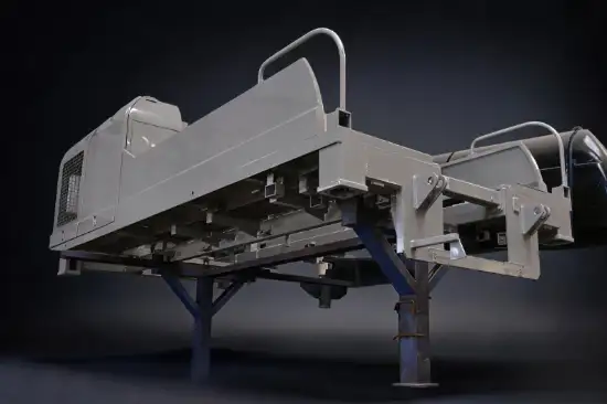
Why the base frame is its own purchasing decision
An equipment base frame, sometimes called a skid or undercarriage, is the structural interface between a machine and the floor, foundation or vehicle it sits on. It carries the machine weight, resists lifting and transport forces, and locates the upper assembly through machined mounting faces. Buyers often treat it as a small part of a larger package, but the base frame sets the datum for everything mounted above it. If its flatness, hole pattern or lifting points are wrong, the whole machine is wrong.
For a custom machinery component manufacturing supplier, a base frame is a made-to-drawing job: plate and section preparation, welding, stress control, interface machining, coating and inspection. The purchasing decision is therefore less about the part shape and more about how much drawing maturity, machining scope and evidence the buyer can define up front.
Drawing and BOM inputs that change the quote
Send the complete context, not an isolated plate drawing. Useful RFQ inputs include the general arrangement, detail drawings, bill of materials, 3D model where available, revision status, and the expected quantity or annual run. State whether the supplier manufactures to released drawings or takes part in a design review, and keep design authority explicit.
Define the drawing hierarchy. When the 2D drawing, 3D model and bill of materials disagree, the RFQ should name the controlling document and mark released, reference-only and provisional files. Without that hierarchy, one bidder prices the current revision while another adds contingency for changes that may never happen.
Machined mounting faces and flatness control
Large welded structures move during fit-up, welding and thermal processing, so one tight tolerance across the whole frame usually raises cost without improving function. Mark the functional datums first. The primary datum is normally the mounting plane or base pads that meet the floor or machine bed, defined after welding and before coating. Secondary and tertiary datums locate the assembly along its length and lock rotation.
General tolerances such as ISO 2768-1 and ISO 2768-2 cover dimensions and basic geometrical features like flatness and perpendicularity when no individual tolerance is shown. They are a baseline, not a substitute for the features that actually matter. Machined mounting faces, bore positions and alignment features need individually specified limits because they control fit and function.
Typical industry practice places as-welded base-plane flatness around 0.5 to 1.0 mm per 300 mm, with machined pads held tighter after post-weld machining. These are planning ranges, not Realjet defaults; the accepted value is a project decision confirmed in the manufacturing scope. If a dimension can only be reached by machining after welding, say so and show the machining allowance on the drawing.
Welding specification and inspection evidence
Do not ask for "good welding" without a defined basis. State the governing welding standard, material group, procedure and personnel qualifications, acceptance level and non-destructive testing scope. For structural work referencing US or Canadian practice, AWS D1.1 is a common reference; ISO 3834-2:2021 defines comprehensive fusion-welding quality requirements for workshop and site work. Weld quality levels such as those in ISO 5817 separate moderate joints from stringent ones used on machine bases and precision pads. Citing a standard does not by itself define the job; the RFQ still sets inspection responsibility and records.
For EU-bound structural steel, execution and CE marking follow EN 1090-1, which affects welding, bolting and documentation. Confirm early whether the project requires it, because the evidence package changes.
List the delivery evidence by inspection point and responsible party: material certificates, weld procedure and personnel records, dimensional reports, NDT reports where required, coating records, and final release documentation. Avoid a generic "quality dossier" because suppliers interpret it differently.
Anchor patterns, lifting and shipping of heavy frames
Base frames are usually the heaviest single item in a shipment, so handling drives both the design and the quote. Define anchor bolt patterns, the centre of gravity, certified lifting points and any transport constraints such as height, width or weight limits. Coating areas that must stay bare for machined faces, threads or ports need clear marking.
Packaging should protect the finished interfaces. Machined faces, threads and coating need suitable covers, and preservation period matters for long sea freight. If delivery is phased, state which documents and loose components travel with each frame.
Where base-frame fabrication sits in contract manufacturing
A base frame is one made-to-drawing component in a wider scope. Realjet provides cutting, forming, welding, machining, coating and inspection for machinery components built to customer drawings, with the final route and responsibilities set in the agreed manufacturing scope. A controlled RFQ, with the same revision set, quantity basis, machining scope and inspection evidence sent to every bidder, gives both sides a clear basis for technical review and price comparison before an order is placed.