
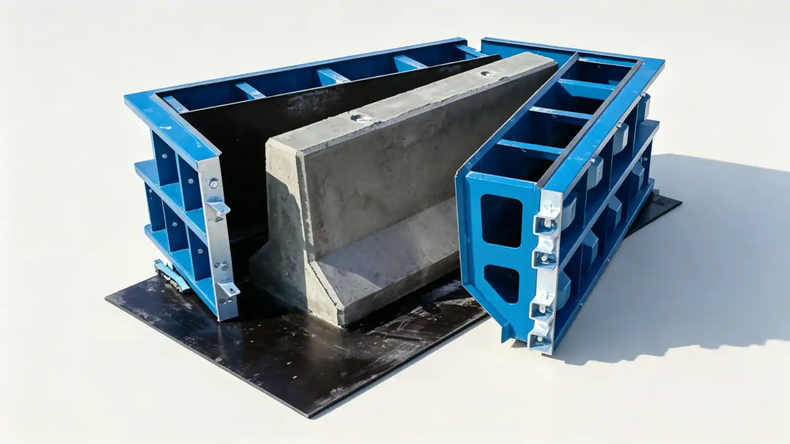
Which barrier and kerb profiles the mould must match
Road barrier and kerb moulds are not interchangeable. The profile is defined by the traffic engineering standard the project follows, and the mould must reproduce that profile consistently over hundreds or thousands of castings. Common concrete barrier profiles include the New Jersey shape, the F-shape, single-slope and vertical wall profiles. Kerb profiles range from barrier kerbs that stop vehicles, through semi-mountable kerbs, to mountable or rollover profiles that allow emergency access.
The choice of profile affects the mould split, the release angle and the surface finish. Safety-shape barriers such as the Jersey and F-shape have a lower sloping face that helps redirect vehicles, but that slope also makes the mould geometry more complex than a vertical wall. The FHWA Roadside Design Guide and state manuals such as the Caltrans or WSDOT design manuals describe these profiles and their applications, and the project specification usually names the required profile by reference. The mould supplier works from the approved profile drawing, not from a generic description.
Geometry, length and joint details to send
The RFQ should include a cross-section drawing of the barrier or kerb with all critical dimensions: overall height, base width, top width, slope angles, toe height and any chamfers or drainage slots. For barriers, specify the section length. Common lengths are 3.0 m, 3.6 m or 6.0 m, but project-specific lengths are frequent. Kerb sections are usually shorter, often 1.0 m to 1.5 m, depending on local standards.
Joint details matter because they determine how sections connect in the field. Precast barriers may be linked with steel pins, wire rope loops, threaded sockets or by butting against adjacent units. The mould must form the recess, hole or cast-in fitting that matches the chosen connection. Kerbs may have tongue-and-groove joints or flat ends. These details must be shown on the drawing or in a separate joint detail sheet.
Lifting and handling provisions also need definition. Barriers are heavy: a 3.0 m section of a standard Jersey barrier can weigh close to two tonnes. The mould must allow lifting inserts to be positioned accurately, and the demoulding sequence must not damage the inserts or the concrete edges. State whether the inserts are supplied and placed by the precaster or whether the mould includes locating features for them.
Mould concept: conventional, hydraulic or movable
For low output or a single profile, a conventional fixed steel mould may be enough. The mould sits on a flat casting bed, the sides are bolted or clamped, concrete is placed and vibrated, and the sides are removed after curing. This is the lowest capital option but may limit cycle time if the sides are heavy or the geometry is complex.
Hydraulic or semi-hydraulic moulds become attractive when output rises or when the profile has deep re-entrant shapes that are hard to strip by hand. Hydraulically operated side forms open in a controlled sequence, reduce manual handling and can improve dimensional repeatability. Movable moulds travel between casting, curing and demoulding stations as part of a circulation system. The right concept depends on the daily output target, the number of sections required and the factory layout.
The mould surface finish and release treatment affect the concrete appearance. A smooth steel surface gives a fair-faced finish; textured liners can match local requirements. The drawing should state the required surface class and any allowable texture variation. The precaster, not the mould supplier, normally chooses the release agent and curing regime, but the mould design must allow both to be applied.
Production rate and surface finish
The RFQ should state the target daily or weekly output and the expected cycle time. A barrier mould can produce one section per day in a simple two-shift operation, but that assumes concurrent reinforcement, concrete supply and curing capacity. If the project needs ten sections per day, the supplier will propose multiple moulds or a circulation concept. Asking for output without stating the available labour, curing method and concrete supply will produce unrealistic proposals.
Concrete strength and age at demoulding also affect the mould design. A barrier that is stripped after 12 to 16 hours needs a mould that releases cleanly without edge damage, and the precaster needs enough mould sets to keep production moving while earlier casts cure. A higher early strength mix may allow faster turnover, but that is a concrete mix decision, not a mould decision.
Surface finish requirements should be realistic. A mould cannot hide poor concrete practice. Specify the acceptable level of blowholes, colour variation and edge defects. If the barrier will be visible and must match an architectural sample, say so in the RFQ so the mould surface and chamfer details can be planned accordingly.
Supplier responsibility and what Realjet needs
Realjet supplies steel moulds and formwork systems for precast concrete components, not the finished barriers or kerbs. The buyer remains responsible for the component design, the structural calculation, the connection details and compliance with the local road authority's requirements. Realjet's role is to turn the approved drawings into a manufacturable mould system and to confirm the operating concept, number of moulds and factory interfaces.
For a road barrier or kerb mould RFQ, send the approved cross-section, the section length range, the joint and insert details, the target output, the concrete mix class and any surface-finish standard. With this information Realjet can propose a mould concept, advise on the number of sets and provide a scope that matches the production plan.
To explore the full range, start from the precast concrete moulds overview, then the municipal and infrastructure moulds category and the road barrier and kerb moulds product page to describe your profile and request a project review.