
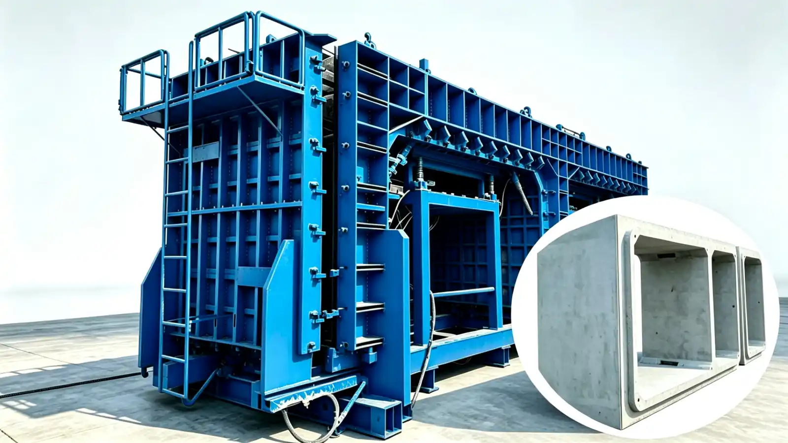
Underground structures such as utility tunnels, subway and road boxes, shaft sections and culvert headwalls are rarely built from a catalogue shape. Each project defines its own geometry, so the steel mould that makes them is engineered around the approved drawings rather than taken from stock. The quality of the mould quote depends almost entirely on the quality of the input package the buyer provides.
This guide lists the inputs needed to scope steel moulds for precast underground structures, and explains which decisions belong to the designer, the buyer and the mould supplier. It is written for owners, contractors and precast producers preparing a request for quotation.
What underground structure moulds cover
The term covers a family of large, often box shaped or shaft shaped components manufactured in a casting yard or factory. Typical members include:
- Utility tunnels and galleries that carry services below ground.
- Road and rail underpass boxes, including multi cell sections.
- Shaft and chamber sections for access, junction or equipment rooms.
- Culvert headwalls and similar transition structures.
These components are usually specified under national or regional bridge and structure codes. In the United States, box sections are commonly designed to AASHTO LRFD Bridge Design Specifications, with product standards such as ASTM C1433 for monolithic box sections and ASTM C1577 for LRFD based design. Segmental box sections are covered by ASTM C1786. Plant quality is addressed by PCI manuals such as MNL-116 and MNL-117. Those documents govern the component, not the mould; the mould is the tool built to cast the approved component.
Why buyers research mould scope before requesting a quote
A mould is project specific. Wall thickness, corner radius, reinforcement access, embedded items, prestressing where used, and the demoulding route all change the mould configuration. A vague enquiry forces the supplier to assume values that may not match the project, which leads to late changes or a mould that does not fit the casting yard.
Researching the scope first lets the buyer compare suppliers on the same basis and write the assumptions into the RFQ. It also separates two questions that are easy to confuse: what the component must be, which is a design decision, and how the mould will make it, which is an engineering decision.
Inputs needed to scope the mould
A complete enquiry package for underground structure moulds should include:
- Approved component drawings, including plan, elevation, section and any typical joint details.
- Component schedule with the range of sizes, lengths and any geometric variations.
- Tolerance basis, stated against the governing standard so the supplier knows which deviations are acceptable.
- Reinforcement and embedded item details, because they affect access, mould division and withdrawal routes.
- Prestressing information where the component is prestressed, since it changes end forms and anchor provision.
- Target output and casting sequence, which influence whether one mould serves many sizes or several moulds run in parallel.
- Yard layout, crane capacity and lifting or transfer interfaces, because the mould must fit the available space and handling method.
- Required operation type, if already decided, or the constraints that point toward a particular choice.
Suppliers also need to know whether the geometry or any naming is proprietary. Generic descriptions are preferred; any protected system name or geometry must be authorised by the customer before it is used.
Operation choices and what drives them
Steel moulds for these components are built as conventional, mechanical, hydraulic or movable systems. The choice follows from the production method, not from a preference:
- Conventional segmented inner and outer forms suit projects where crane access and demoulding clearance allow direct handling.
- Mechanical or hydraulic movement suits repeated inner form or side form movement, where manual handling would be slow or unsafe.
- Movable or station based arrangements suit production stations connected by rails, foundations and utilities.
None of these is better in the abstract. They trade capital cost, cycle time and yard space against each other, and the right answer depends on the output target and the site. The supplier should explain the trade off in the proposal rather than default to one type.
Responsibility boundaries
Keeping the lines clear avoids disputes during manufacture and casting:
- The designer owns the component geometry, tolerances and acceptance criteria. The mould is built to the approved drawings.
- The buyer owns the project inputs, the production plan and confirmation that the proposed mould fits the yard and the handling equipment.
- The mould supplier owns the steel engineering, the division and locking system, the withdrawal sequence and the interfaces for reinforcement, embedded items and lifting.
Final component tolerances and acceptance remain subject to the approved project documents and applicable standards. The mould supplier does not set the structural requirements; it delivers the tool that casts to them.
Where to start
Begin from the component, not the mould. Confirm the approved geometry and the production brief, then open a review with a supplier who engineers project specific steel systems. Realjet develops precast concrete moulds across bridge, building, tunnel, municipal and special applications, including the tunnel and underground mould category. The underground structure moulds product page shows the typical configuration directions for shafts, utility galleries and similar structures.
Send the controlled drawing set, the component schedule and the yard constraints. A supplier can then return a mould concept with the operation type, the division scheme and the open questions, so the RFQ compares like for like.