
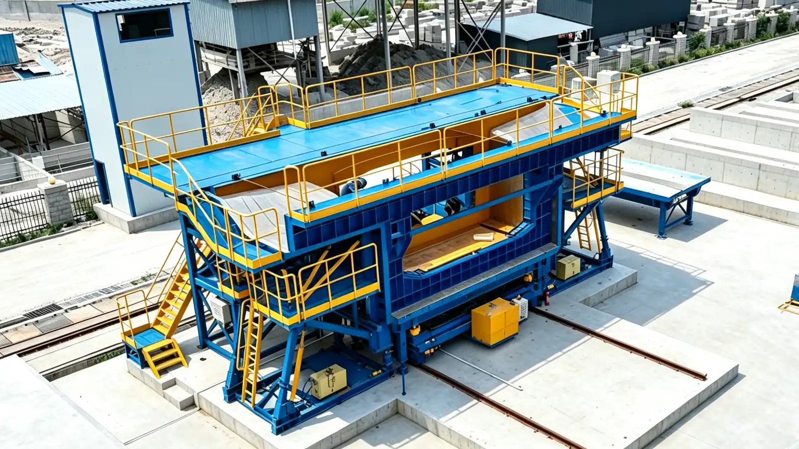
What a segmental box girder mould is for
A segmental box girder bridge is built from short precast concrete segments, post-tensioned together to form the girder. The mould makes each segment to the approved cross-section, with the webs, diaphragms, shear keys and post-tensioning ducts in the right place. The segmental box girder mould systems from Realjet are engineered around the approved section, the casting method and the yard layout, not as a catalogue product.
Segmental construction is used for spans that repetition and geometry make uneconomic to cast in place: viaducts, river crossings and urban rail. Erection methods include span-by-span, balanced cantilever and incremental launching. The mould has to serve the method you choose, because the casting sequence and the handling route follow from it.
Why match casting drives the mould design
The defining feature of segmental work is match casting. Each segment is cast against the face of the one before it, so the two joint faces are geometrically complementary. When the segments are later brought together and post-tensioned, they fit despite the small angular and positional errors that accumulate during casting. The PCI Recommended Practice for Segmental Construction and FHWA bridge guidance describe the method and its tolerances.
This has direct consequences for the mould. The bulkhead that forms the match face must hold position to the casting curve, and the tool must form the male and female shear keys that interlock across the joint. Post-tensioning duct sleeves must sit where the designer placed them, because a duct that drifts blocks the tendon. Survey references on the mould let the casting team set each segment in six degrees of freedom: three translations and three rotations.
Tolerances are tight because they protect the whole bridge. Reference practice such as IRC SP 65 gives match-cast segment length at plus or minus 5 mm non-cumulative, shear key position at plus or minus 5 mm, tendon duct location at plus or minus 3 mm, and edge or soffit grade at plus or minus 1 mm per metre. Erection tolerances limit the deviation between outside faces of adjacent segments to about 6 mm. Your RFQ should state the tolerance class your design requires rather than assume a default.
Inputs to prepare before requesting a quote
Before a supplier can engineer the mould, prepare:
- The approved segment geometry: cross-section, length family, web and diaphragm arrangement, and any special features.
- The erection method, because it sets the casting sequence and handling route.
- The casting method, short-line or long-line, and the number of segments and casting cells.
- The bridge alignment data: horizontal curvature, vertical grade and superelevation, as casting tables the mould must follow.
- Shear key and post-tensioning duct details, including positions, sizes and any couplers.
- Concrete strength, curing method and any release-strength requirement.
- The tolerance class and the survey-control method.
- Demoulding method: inner-form withdrawal, side-form opening and the lifting interfaces.
- Handling, transport and site limits that affect mould division and weight.
- The local standards and any owner-specific requirements.
The bridge and transportation mould systems overview covers the families these inputs apply to, and the full Realjet precast concrete moulds range shows where a segmental tool sits among them.
How responsibility is split between designer, buyer and supplier
The mould is a project tool, so the lines of responsibility matter.
The designer provides the segment geometry, the casting curve, the match-cast tables and the tolerance specification. The buyer confirms the erection and casting method, the yard layout and the lifting equipment, and supplies the approved drawings. The supplier engineers the mould to that geometry and sequence, provides the positioning and adjustment functions, forms the shear keys and duct sleeves, and builds in the survey references.
No party should assume the others' work. A supplier cannot quote a match-cast tool from a single cross-section drawing, and a buyer should not expect the tool to correct a geometry the design never supplied. Writing these boundaries into the RFQ prevents the rework that comes from silent assumptions.
What to verify in a supplier's proposal
When proposals come back, check that the mould scope matches the inputs you sent:
- Does the bulkhead and adjustment system cover the full casting curve, including curvature and superelevation?
- Are shear keys and duct sleeves formed to the designer's positions, with allowances for withdrawal?
- Is the demoulding route realistic for the segment weight and the available crane?
- Does the proposal state the tolerance the tool is built to, and the inspection evidence you will receive?
- Are survey references and datums included so the casting team can set each segment correctly?
A proposal that quietly drops one of these, or treats the match face as a fixed bulkhead, will not produce segments that fit on site.
Next step: review the mould with the supplier
The RFQ inputs above are the basis for a useful supplier discussion. Bring the approved geometry, the alignment data and the tolerance class, and ask each supplier to show how its mould will hold the match-cast fit across the full bridge. From there, the segmental box girder mould systems page is the place to review Realjet's specific tool and start a project conversation.