
Where U-girders fit in urban rail and viaduct work
A U-girder, also called a U-beam, is a precast concrete girder with a U-shaped cross-section. The webs form side walls that can contain the rolling stock partly below the top of the girder, which gives a lower overall structural depth than many box or T-girder alternatives. That lower depth matters in dense urban corridors where clearance, noise and visual impact are tightly controlled.
U-girders are used on elevated metro, light-rail and urban viaduct projects. The shape provides some inherent shielding of wheel noise and creates an emergency evacuation walkway along the open top of the girder. Because the section is deeper than a slab but shallower than a conventional box girder for the same span, it suits routes with limited vertical headroom.
From a procurement point of view, the mould is project-specific. The inner and outer geometry, the span range, the prestressing layout and the embedded items all change with the bridge design. The buyer's job is to package enough information so the mould supplier can quote a system that fits the approved component and the intended casting yard.
What a U-girder mould must do
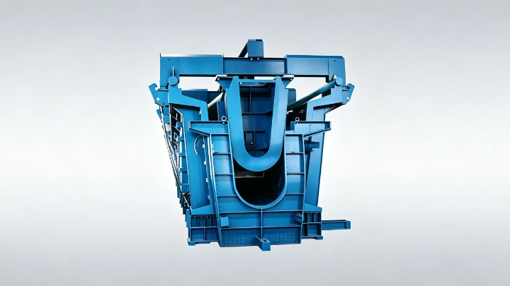
A U-girder mould is more than an outer shell. It is a steel system that holds the concrete in the U-section while giving access for reinforcement, concrete placement, vibration, curing and demoulding.
Outer side forms
These define the outer faces of the two webs and must open far enough to clear the finished concrete during demoulding.
Inner form
This creates the hollow centre of the U-section. Because the cavity is enclosed on three sides, the inner form must fold, collapse or translate out of the girder without damaging the surface.
Bottom form
The soffit supports the bottom slab of the U-girder and must stay flat under the weight of wet concrete and prestressing forces.
End forms
These close the ends of the mould and usually contain inserts for bearings, anchorages or diaphragms.
Working platforms, access ladders and vibrator mounts
These are part of the operating package, not extras that can be left out later.
The opening sequence is the detail that separates one mould concept from another. The side forms can hinge outward, the inner form can retract hydraulically, and the bottom form can be fixed or split depending on how the girder will be lifted out. The choice depends on crane access, the demoulding envelope and the cycle time target.
Project inputs to send with the RFQ
The mould supplier cannot size or price the system without the following:
Approved U-girder drawings
Include the typical cross-section, the span schedule, any haunches or transitions, and the location of construction joints. If the girder varies along the length, state how many variations there are and whether they are handled by inserts, adjustable forms or separate moulds.
Reinforcement and embedded-item details
Bar schedules, mesh layouts, prestressing duct positions, anchorages, lifting inserts, rail fixings, drainage details and bearing plates all affect the formwork clearances and the access openings needed during casting.
Prestressing information
U-girders are usually pretensioned or post-tensioned depending on the design. State the strand or tendon layout, the tensioning method and whether the stressing bed is part of the mould scope or a separate line item.
Target cycle time and weekly output
This determines whether a manually operated segmented mould is sufficient or whether a hydraulic inner-form retraction and automated side-form opening are justified.
Demoulding and handling plan
Define how the finished girder will be lifted, which direction it will move, and the available clearance around the mould. A mould that opens perfectly but blocks the crane path is not useful.
Factory layout and foundation data
Rail-guided or station-based mould systems need level rails, utility trenches and pit details. Conventional moulds need hard standing and crane coverage. Send a layout drawing with bay dimensions, column grids and hook coverage.
The Realjet U-girder moulds product page lists the same input set from the supplier's side.
Operating choices that affect the quote
Most U-girder moulds fall into one of three operating concepts. The choice affects price, delivery and the skill level of the crew.
| Concept | When it suits | What to review |
|---|---|---|
| Conventional segmented mould | Crane access is good and the movement envelope is simple | Panel division, locking, support and withdrawal sequence |
| Hydraulic opening system | Coordinated inner or side-form movement is needed for speed or access | Cylinder stroke, synchronisation, controls, safety and maintenance |
| Rail-guided or station-based system | The mould must move between fixed production stations | Rails, foundations, utilities, transfer logic and interfaces |
A conventional mould is usually the lowest first cost and the slowest cycle. A hydraulic system reduces manual labour and cycle time but adds maintenance and a power pack. A rail-guided system is attractive when the same mould passes through cleaning, reinforcement, casting, curing and demoulding positions, but it needs civil works and alignment accuracy that the buyer must provide.
For urban rail projects, the choice is often driven by site constraints. A cramped casting yard may favour a compact hydraulic mould; a dedicated precast plant with multiple lines may prefer a rail-guided arrangement.
Tolerances and acceptance evidence to agree
Dimensional tolerance, surface finish and joint geometry should be agreed before manufacture starts. Common references include PCI MNL-117 for precast concrete tolerances, project-specific specifications and the approved bridge drawings. Do not assume that a general steel-fabrication tolerance applies to a concrete mould; the finished component tolerances come from the concrete product requirements, not from the steel workshop alone.
Agree the following evidence before manufacture starts:
Design calculation package
Structural checks for the mould under concrete pressure, vibration and lifting loads.
Trial assembly or first-off report
A full-size trial assembly confirms that the forms close, seal and open around a mock reinforcement or a first casting.
Material certificates
Steel grades, welding consumables and any bought-out hydraulic or electrical components should come with traceable documentation.
Weld inspection records
Depending on the project, this may include visual inspection, dimensional reports and NDT for critical seams.
As-built geometry records
These help reconcile the mould with the finished girders and are useful if modifications are needed later.
Where a U-girder mould sits in Realjet's range
U-girder moulds are part of the Bridge and Transportation Moulds family. Within that family, Realjet lists a dedicated U-girder moulds product page. The page describes conventional, hydraulic and rail-guided configuration directions and confirms that Realjet reviews standalone moulds as well as coordinated production arrangements.
If your project uses U-girders for an elevated rail or road viaduct, start the mould RFQ with the approved drawings and a clear statement of the casting method. Realjet can then review the mould concept, the operating sequence and the interfaces with handling, curing and any wider production-line scope.