
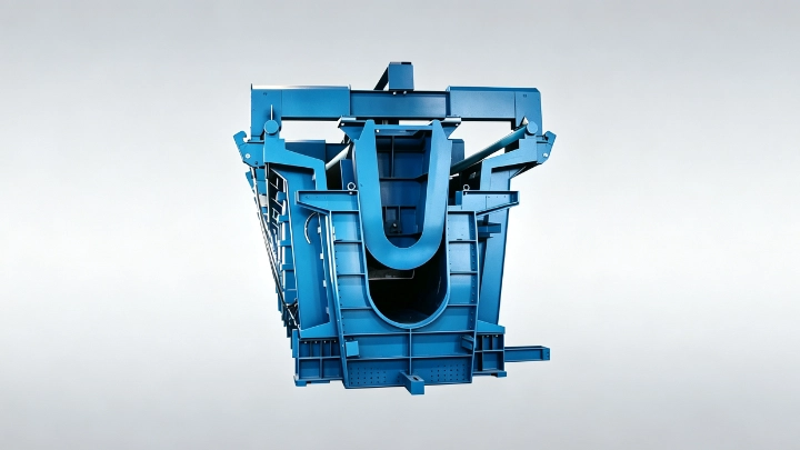
Why side formwork operation matters for U-girders
A U-girder, also called a U-beam, has a U-shaped cross-section with two vertical webs. The side forms define the outer faces of those webs and must open far enough to clear the finished concrete during demoulding. In a U-girder mould the side formwork is not a minor detail; it controls how the mould releases the beam, how fast a cycle runs, and how much manual effort the crew spends per casting.
The U-girder moulds product page and the wider bridge and transportation moulds family describe U-girder moulds as project-specific steel systems. Within that, the operating method for the side forms is one of the first decisions a buyer should make, because it shapes cost, utilities and the skill level of the crew.
Hydraulic versus mechanical side formwork
Mechanical side formwork relies on manual or crane-assisted movement: hinges, screw jacks, wedges and locking pins. It is usually the lower first cost and the simpler system to maintain, but it needs more manual labour and more time per opening and closing cycle. Hydraulic side formwork uses cylinders to drive the side forms outward or inward with controlled motion. It reduces manual effort and supports faster, repeatable movement, but it adds a power pack, hoses, controls and a maintenance obligation.
The choice is not only about speed. It is about whether the demoulding envelope, the beam length variation and the available crew justify powered assistance. A compact urban casting yard with tight clearance often favours hydraulic side forms; a plant with good crane access and simpler beams may do well with mechanical operation.
Stroke, synchronisation and control
If hydraulic side formwork is chosen, the buyer must specify the movement the cylinders must achieve. The cylinder stroke has to clear the finished web without interference. For moulds with long side forms, several cylinders act along the length, and their movement should be synchronised so the form stays parallel and does not skew the beam or bind in the guides.
Control matters as much as force. The system should let the operator move each side form to a defined position and hold it there during casting. Mechanical stops and locks remain important because hydraulic pressure alone should not be treated as the only means of securing a mould during production work. Ask the supplier to state the cylinder force, mounting angle, pivot locations, support reactions and locking method, and to show how they are matched to the concrete pressure and the release sequence.
Locking, safety and maintenance access
Side formwork is a load-bearing part of the mould during casting, so locking is a safety function, not a convenience. Define the lock type, the verification the operator performs before concrete placement, and the access needed to inspect locks and seals. Hydraulic systems add items that mechanical ones do not: hose routing, cylinder protection from concrete and vibration, and service access for the power pack.
Maintenance access should be planned into the layout, not added later. A hydraulic side form that is fast to open but hard to service will cost more over the project than a simpler system that the crew can keep in good condition. State the expected number of casting cycles and ask how the supplier expects the side-form mechanism to be inspected and maintained.
How the choice affects demounting and cycle time
Demoulding sequence is the link between side-formwork operation and output. Mechanical side forms need manual release of each lock and careful swinging of the form clear of the beam; the time scales with beam length and the number of locking points. Hydraulic side forms shorten that step but depend on reliable power and a clean control routine. Either way, the side form must clear the demoulding envelope defined by the crane path and the handling plan.
Cycle time is therefore a system result, not a side-form feature alone. It depends on the inner-form withdrawal, the bottom-form arrangement, curing, and how the finished beam is lifted out. When comparing quotes, ask each supplier to state the assumed opening and closing time for the side forms and the basis for that assumption, so the numbers are comparable.
Where to start the side-formwork specification
Start from the approved U-girder drawings: the cross-section, span schedule, web geometry, prestressing layout and embedded items. Then state the demoulding envelope, the available crane access, the target cycle time and the crew skill level. With those inputs, the supplier can recommend mechanical or hydraulic side formwork and show the stroke, synchronisation, locking and maintenance provisions.
Realjet reviews U-girder mould concepts, including side-form operation, against the approved section and the production layout. Buyers should confirm the operating sequence, the interfaces with inner and bottom forms, and the handling plan before manufacture starts, so the side formwork supports the whole mould rather than complicating it. The precast concrete moulds overview lists the broader mould families for context.