
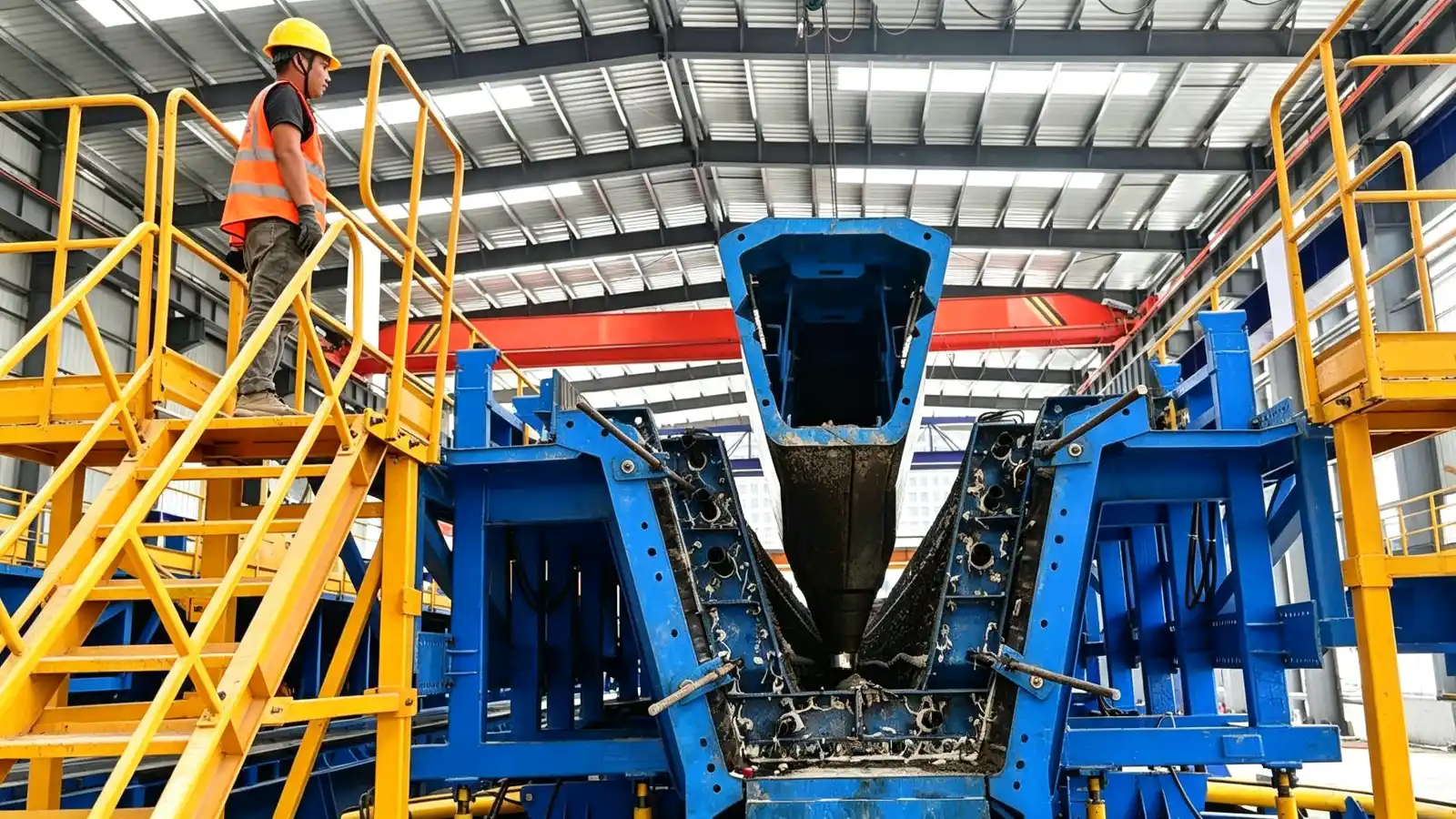
A box girder is defined by its hollow section
A precast box girder is a concrete bridge member with a hollow box-shaped cross-section. The top and bottom slabs form the horizontal parts of the section, while the side walls act as webs. The void reduces concrete volume and self-weight compared with a solid member of the same outside dimensions.
The word "box" describes the cross-section. It does not identify one fixed product. A girder may have one cell or several cells. It may be cast as a complete transportable member, produced as a full span, or divided into segments that are assembled and post-tensioned as part of the bridge. The approved bridge design decides the section, reinforcement, prestressing, joints and erection method.
FHWA describes prestressed concrete box beams as longitudinal box-shaped members with circular or rectangular voids. Its bridge guidance also distinguishes adjacent box beams from other concrete box girder systems. This matters in an enquiry because "box beam" and "box girder" do not always identify the same component or production method. See the FHWA overview of concrete beam and girder bridge types.
Box girder, box beam and segmental girder are not interchangeable
Project language varies by country and design authority. Buyers should send the section drawing instead of relying on a product name.
An adjacent box beam is usually one of several narrower precast units placed side by side and connected across the bridge width. A larger box girder can be a single-cell or multi-cell superstructure member with a different deck, diaphragm and prestressing arrangement. A segmental box girder divides the bridge superstructure into shorter precast units that are joined during erection.
These products may look related in a catalogue, but their factories are not configured on the same basis. A full-length member needs a mould and handling route for the complete girder. Segmental production needs controlled joint geometry and, when specified, match-casting between successive segments. Adjacent units create another set of mould quantity, connection and handling decisions.
The buyer should therefore identify:
- the exact product family and governing drawing;
- whether the unit is full-length, full-span or segmental;
- single-cell or multi-cell geometry;
- casting orientation and joint concept;
- prestressing method and approved sequence;
- finished weight and planned lifting points.
Why engineers select a box section
The structural designer selects the bridge type. The production-line supplier does not decide whether a project should use a box girder.
The closed section can provide torsional stiffness and gives the designer space to arrange webs, slabs, diaphragms and prestressing tendons around the hollow cell. FHWA's Post-Tensioned Box Girder Design Manual shows single-cell and multi-cell forms and discusses torsional stiffness as one characteristic of box girder construction.
Those general characteristics do not establish a mould specification. The production equipment must follow the approved geometry, including web inclination, slab thickness, diaphragms, tendon ducts, anchor zones, embedded items and access openings.
How a box girder is produced
The production sequence depends on the chosen girder type, but a typical planning study covers mould preparation, reinforcement and duct installation, internal-form setup, concrete placement, curing, prestress transfer or post-tensioning activities, demoulding, inspection and transfer.
The internal void makes formwork planning especially important. External side forms create the outside faces. An internal form creates the cell. End forms control the girder ends, diaphragms, joints and tendon interfaces. The mould division must allow reinforcement installation, concrete access and removal of the internal form after the concrete reaches the authorised release condition.
For segmental construction, the buyer must also define joint geometry and casting method. Match-casting uses the face of a previously cast segment to form the mating face of the next segment. This changes the mould arrangement, survey controls, segment movement and production sequence.
What the girder choice changes in a production line
A precast box girder production line is planned around the actual component, not a generic daily-output target. The girder geometry affects several equipment decisions:
| Production decision | Box girder input |
|---|---|
| Mould concept | External geometry, internal cell, end forms and opening sequence |
| Prestressing | Pretensioning or post-tensioning requirements and approved force path |
| Concrete placement | Access to webs, slabs, diaphragms and congested reinforcement zones |
| Curing | Occupied time, temperature-control method and release criteria |
| Handling | Finished weight, lifting points, turning restrictions and transfer route |
| Inspection | Datums, joint faces, ducts, embedded items and dimensional records |
A production line for short segments may use repeated stations and segment transfer. A line for full-length or full-span girders faces different mould occupancy, crane capacity and transport limits. Suitability depends on the bridge design, erection schedule, factory site and local logistics.
What a box girder mould must control
Buyers comparing precast concrete mould systems can first review the Bridge and Transportation Moulds category. The exact product reference is the published box girder mould page.
The mould RFQ should include the approved girder drawings, component schedule, casting orientation, prestressing details, reinforcement and embedded-item information, target cycle, tolerance basis, factory layout and lifting method. It should also state whether side or internal forms need mechanical, hydraulic or movable operation.
Ask the supplier to show how the proposed mould opens and closes, how each section is referenced, how the internal form is removed, and which dimensions are checked during trial assembly. A hydraulic function should solve a defined movement or access problem. It should not be added merely as an automation label.
Information to send before requesting a line proposal
Start with the structural designer's current documents. Mark every drawing revision and separate approved information from preliminary assumptions. Then add the production requirements that the equipment supplier cannot obtain from the girder drawing:
- quantities by girder type and delivery sequence;
- working calendar, shifts and target accepted output;
- proposed concrete supply and curing method;
- factory dimensions, crane coverage and utility conditions;
- storage, finishing and dispatch arrangements;
- erection or transport limits that affect production order;
- buyer and supplier delivery responsibilities;
- applicable inspection and acceptance documents.
Realjet supplies project-specific moulds and production-line equipment for precast concrete components. It does not supply or structurally design the box girders themselves. Sharing the approved product definition together with the output and site brief allows the initial proposal to address the correct mould, process and handling concept before the buyer fixes the equipment package.