
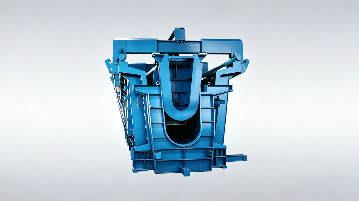
A U-girder has an open-top cross-section
A precast U-girder is a bridge member with a bottom slab and two side webs that form an open U-shaped section at the production stage. The webs may be vertical or inclined, and their upper edges provide interfaces for the deck or other structural details defined by the bridge designer.
The name covers a family of shapes. Girder depth, width, web angle, end blocks, diaphragms, prestressing and deck connection vary by project or design authority. TxDOT, for example, has a dedicated bridge design manual section for pretensioned concrete U-beams. A buyer still needs to issue the standards and drawings that govern its own project instead of adopting another authority's section.
How a U-girder differs from a box girder
The clearest difference during precasting is the top of the section. A U-girder is open. A box girder has a closed hollow section, although a U-shaped precast member may later work with a deck that changes the completed structural system.
This difference changes the mould. A U-girder usually needs a bottom form, external side forms, an inner form between the webs and end forms. The inner form is accessible from above, but it must still clear reinforcement, prestressing details, diaphragms and the hardened concrete during withdrawal. A closed box section may require a more enclosed internal-form arrangement.
Names alone can mislead. Some project teams use "U-beam" while others use "U-girder." The governing section drawing and structural notes decide what is being produced. A supplier quotation should repeat the drawing reference and product identifier rather than translate it into a preferred catalogue term.
Where U-girders are used
U-girders appear in bridge and viaduct systems where the approved design uses a trough-like precast member with a separate or subsequent deck arrangement. The project may use pretensioning, post-tensioning or a combination defined by the engineer. Bearings, deck connections, diaphragms and erection bracing also come from the structural design.
Published standards do not make every U-girder interchangeable. TxDOT's Bridge Design Guide includes specific guidance for pretensioned concrete U-beams, such as deck and bearing-seat detailing. The equipment supplier therefore needs the full project detail set. A cross-section by itself does not show every manufacturing interface.
How the open section affects production
The open top can provide direct access for installing reinforcement, embedded items and the inner form. It also leaves several practical questions for the production planner:
- how the inner and outer forms open or move;
- whether reinforcement is assembled inside the mould or placed as a cage;
- how concrete reaches the bottom slab and both webs;
- where vibration equipment and inspection access are located;
- when the inner form can be withdrawn;
- how the girder is lifted without damaging edges or changing the approved support condition.
The production sequence must follow the concrete mix, prestressing method, curing plan and authorised release criteria. Equipment automation cannot set those engineering requirements. It can carry out defined movements, record selected process data or reduce manual handling when those functions are included in the agreed design.
What changes in a U-girder production line
A precast U-girder production line must coordinate the mould with reinforcement, prestressing, concrete delivery, curing, demoulding and transfer. The buyer should compare proposals against the same girder family and production calendar.
| Line decision | U-girder information required |
|---|---|
| Mould arrangement | Inner, outer, bottom and end-form geometry |
| Opening method | Movement direction, clearance, access and locking points |
| Prestressing | Tendon or strand arrangement, force path and operating sequence |
| Casting | Concrete access, layer sequence, vibration and finish requirements |
| Curing | Mould occupancy, release basis and environmental controls |
| Transfer | Girder weight, lifting points, support locations and factory route |
An equipment proposal should show which stations operate concurrently and which resources are shared. A crane, hydraulic power unit or transfer route can become a constraint even when each individual machine appears fast enough. The target should be accepted girders on the required calendar, not an isolated machine cycle.
What to specify in a U-girder mould RFQ
The precast concrete moulds homepage explains the wider product range. U-girders belong to the Bridge and Transportation Moulds category, and the exact published reference is the U-girder mould product page.
Send the supplier approved U-girder drawings, the section and length schedule, reinforcement and embedded-item details, prestressing information, target cycle, factory layout and lifting plan. Add the required operating preference only after checking local skills, available space and maintenance support.
The supplier should return a mould division drawing and operating sequence. It should identify fixed and moving parts, setup datums, locking points, hydraulic functions if proposed, changeover work and the inspection evidence included before shipment. If one mould is expected to cover several girder sizes, the quotation should show which geometry changes and how each configuration is verified.
Questions buyers should settle before equipment selection
The product definition comes first. Confirm these points with the bridge designer and precast production team before asking for a final line price:
- Which U-girder types and drawing revisions are approved?
- What quantities and delivery sequence must the factory support?
- Which prestressing and curing processes govern mould occupancy?
- What crane capacity, floor space and movement routes are available?
- Which dimensions, interfaces and records control acceptance?
- What work belongs to the mould supplier, line supplier and buyer?
Realjet develops project-specific moulds and production-line equipment around approved component information. It does not select the bridge system or sell the U-girders produced by the line. A complete drawing package and production brief allow the equipment discussion to focus on form movement, process sequence, output and factory interfaces before the purchasing scope is fixed.