
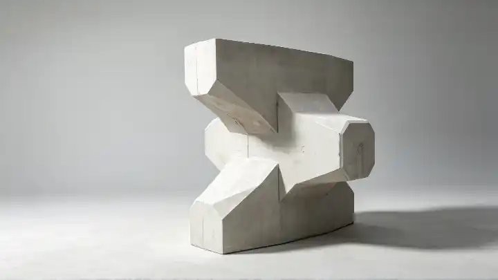
What is an interlocking concrete armour unit?
An interlocking concrete armour unit is a shaped precast element used in the outer layer of some breakwaters, revetments and coastal-protection structures. Its projecting forms interact with neighbouring units and the armour slope. The project designer selects the unit system, size, placement pattern and hydraulic design for the specific coastal conditions.
The mould is the reusable production tool that forms the approved geometry. An armour unit may have projecting legs, tapered surfaces and undercut relationships. Its mould has to divide and open in a sequence that releases the concrete instead of forcing the finished unit through a trapped shape.
The wider precast concrete mould range includes bridge, tunnel, building, municipal and marine applications. For this purchase, the relevant family is the Marine and Coastal Moulds category, not a general bridge or block mould.
The approved unit geometry comes first
The mould manufacturer should not select or recreate an armour-unit system from a photograph. The buyer needs to provide the approved three-dimensional geometry, controlled drawings, unit volume or mass, material requirements and any licensed design information required by the project.
Some armour-unit systems are proprietary. A generic description of an interlocking unit does not grant the right to manufacture a protected design or use its trade name. Realjet's published Accropode moulds page states the same limit: project documentation and naming must follow the rights and approvals supplied by the customer.
The US Army Corps of Engineers publishes its Coastal Engineering Manual as engineering guidance for coastal processes and shore-protection projects. Mould procurement does not replace the coastal designer's hydraulic model, stability analysis, structural review or placement specification.
Why the mould is split into sections
The concrete unit must remain supported during casting and curing, yet the steel shell must move away after release. Mould segments are arranged around the approved geometry so that joints, locks and opening directions permit demoulding. The number and shape of those segments depend on the unit, casting orientation, available lifting equipment and production method.
A buyer should ask the supplier to show the opening sequence before approving the design. The review should answer several practical questions:
- Which panel or segment opens first?
- Are any faces trapped until another panel moves?
- What supports the concrete unit as the mould opens?
- Which parts are lifted by crane, and which remain on the base?
- Where can workers reach locks, joints and cleaning surfaces?
- How is the mould returned to its casting position and checked before the next cycle?
Mechanical locks may suit one arrangement, while another may justify hydraulic movement. Hydraulics are not automatically faster or safer. They change the power, controls, guarding, maintenance and interface scope. Buyers should compare that added scope against the actual mould quantity and cycle instead of requesting hydraulics as a label.
Choose the casting orientation with the production method
Casting orientation affects concrete placement, vibration access, visible surfaces, joint locations and demoulding. It also changes how reinforcement or embedded lifting provisions are held, where air may be trapped and how the unit is supported after release.
The RFQ should identify the approved concrete placement method, vibration method, access envelope and surface acceptance criteria. If the project requires a particular face to remain free of a mould joint, show that on the drawing. If joint marks are permitted in defined areas, state those areas instead of asking the mould supplier to guess.
Handling must be reviewed at the same time. Provide the approved lifting points, unit mass, centre of gravity, crane capacity, turning method and route to the curing or storage area. The mould opening sequence is only workable if the released unit can leave the base without colliding with panels, platforms or adjacent moulds.
Calculate mould quantity from the cycle
Mould quantity depends on target output and the time each mould remains occupied. Map preparation, reinforcement or insert setting, closure, concrete placement, curing, opening, lifting, cleaning and inspection. Some work may occur outside the mould. Other work keeps the tool unavailable.
Use accepted units per working day as the output target, then account for shifts, curing basis, planned product mix and production allowance. Do not divide daily output by one assumed cycle without checking which operations can overlap. If a project uses more than one unit size or geometry, list the quantities and casting sequence for each type.
The quotation should state the assumed cycle and show which buyer inputs support it. Concrete strength development and demoulding approval remain with the project's authorised concrete and quality personnel. A mould supplier can design around a stated release condition but should not invent one to make the equipment count look smaller.
Specify joints, seals and contact surfaces
Repeated casting puts practical demands on the steel shell. The design review should identify contact plates, stiffeners, base support, panel joints, locks, lifting points and replaceable or adjustable items where applicable. Buyers should define the dimensional inspection basis and the surfaces that control the finished unit geometry.
Joint and sealing details need enough pressure and alignment control to limit unacceptable grout loss, but the acceptance requirement must come from the project specification. Ask how the supplier will inspect fit-up during workshop assembly and how site reassembly will reproduce the same references after shipping.
Surface treatment also needs a boundary. Concrete-contact faces, external steelwork, hydraulic components and fasteners may require different preparation or protection. The RFQ should state what coating is permitted, which surfaces remain uncoated, and how the mould will be packed for its transport and storage conditions.
What to send with an armour unit mould RFQ
A useful enquiry package includes:
- authorised 3D geometry and controlled 2D drawings;
- confirmation of design rights or licence information where required;
- unit size, volume or mass and material specification;
- target accepted output, working calendar and planned mould quantity basis;
- casting orientation, concrete placement and vibration method;
- curing method and authorised demoulding condition;
- approved lifting points, crane data, turning method and storage route;
- dimensional and surface acceptance requirements;
- preferred mechanical or hydraulic operation, if already decided;
- required workshop assembly, inspection, documents and delivery scope.
Ask bidders to list every assumption and deviation. The proposal should distinguish mould supply from civil foundations, cranes, concrete equipment, curing systems, installation work and production support. It should also state whether trial assembly, functional checks, spare seals, special tools or site supervision are included.
Realjet reviews project-specific moulds from the approved unit geometry and production plan. Send the unit type, main size or mass, required output, drawing status and handling concept through the precast concrete mould enquiry route so the response can address the correct marine mould and delivery boundary.