
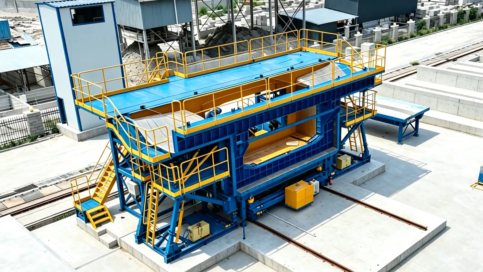
Why match casting depends on the mould
Match casting is the defining method for precast segmental bridges. Each segment, after it is cast, becomes the form for the next segment, so the joint faces are geometrically complementary and the pieces fit during erection despite small casting errors. The mould is what holds that geometry, so the tolerances you set for the mould decide whether the segments will match in the yard and on the bridge.
This article is about what to specify when you order the mould, not about the bridge as a product. Realjet supplies segmental box girder mould systems to customer geometry, not the cast segments.
Joint face flatness and tolerance
The match-cast joint face is the surface that mates with the adjacent segment. Industry guidance such as the TarmacView segmental construction glossary cites match-cast precision around plus or minus 1 mm as the typical target, with microscopic surface variation of 0.1 to 0.3 mm across the face filled by the epoxy layer. PCI's Recommended Practice for Segmental Construction in Prestressed Concrete treats the final erected geometry as the governing acceptance item rather than any single face measurement.
Those figures are guidance, not a specification Realjet sets. The exact face flatness and overall tolerance come from the bridge design and the erector's method. State the number you require in the RFQ, and ask the supplier to confirm the mould can hold it through repeated casting and demoulding.
Shear keys and epoxy joints
Most segmental joints carry male and female shear keys on the face. The keys interlock during erection and transfer shear with the post-tensioning compression, so their depth, width and position must be controlled in the mould. The epoxy joint, often called a Type A joint in the AASHTO and ASBI classification, is normally 0.5 to 1.5 mm thick after compression and fills the surface irregularities so bearing is uniform across the section.
The mould must reproduce the key profile and the face every cycle. When you brief the supplier, define the key geometry, the Epoxy bond detail and any waterstop or gasket seat, because these are mould features, not field fixes.
Survey references and geometry control
Match casting is controlled by survey, not by eye. Control points are cast into each segment as concrete is placed, and the next segment is positioned relative to the as-cast one in six degrees of freedom using the bridge alignment data. PCI geometry-control case studies show match-cast set positions held to roughly 0.9 mm transverse and a few millimetres side to side, with the acceptable value set by what the equipment can hold.
For the mould, this means the bulkhead, side and bottom structures need fixed and adjustable references, and the supplier needs the casting geometry tables from the designer. Ask whether the mould provides the adjustment and locking functions the survey method requires, and who sets the reference values each cycle.
Short-line versus long-line mould systems
The mould concept follows the casting method. A short-line system casts one segment against a controlled match-cast reference, with bulkhead positioning and survey points built into the mould. A long-line system casts several segments along an approved line and yard arrangement. The choice changes the mould size, the adjustment hardware and the handling space, so it should be agreed before the mould is detailed.
Our overview of the segmental match-casting method explains the casting sequence in more detail. Read it together with this article when you prepare the mould brief.
Designer versus supplier responsibility
The responsibility split should be written into the RFQ. The designer or buyer defines the segment geometry, the match-cast tolerance, the shear-key profile, the epoxy joint detail and the survey control points from the bridge alignment. The supplier manufactures the mould to hold that geometry, provides the adjustment and reference system the method needs, and records the as-built mould accuracy.
Realjet's segmental box girder mould systems are engineered as conventional, hydraulic or movable systems around the geometry, casting sequence and yard requirements you confirm. The tolerance the mould must hold is the one your specification states, not a value assumed by the supplier.
Choosing the right mould family
Segmental bridge moulds sit within the bridge and transportation mould category, alongside T-girder, box girder, I-girder, U-girder and trough girder systems. Browse the precast concrete moulds overview to see the full range, then open the category page for the segmental options.
Next step
Match casting succeeds or fails at the mould. Define the joint-face tolerance, shear-key geometry, epoxy detail and survey references in the RFQ, and confirm the mould's adjustment and reference system can hold them.
Realjet's segmental box girder mould systems are built to the geometry and match-cast tolerance you specify, as part of production lines and equipment for precast concrete components.